Great job Ryan! My new AC transformer showed up yesterday and I designed a new enclosure to print so hopefully I'll repackage mine this weekend.
From your pics, everything looks great. In some pics it looks like the blue (AC) wires are going to the top terminals on the switch. But in another it looks like there are green leads going to those terminals. It should be the output from the larger board (DC) that feeds the top terminals on the switch.
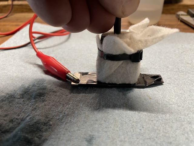
One issue I see is your pad. I think you'll have a hard time getting good results with no pressure on it. I keep a fair amount of force down on mine to ensure a consistent etch everywhere:
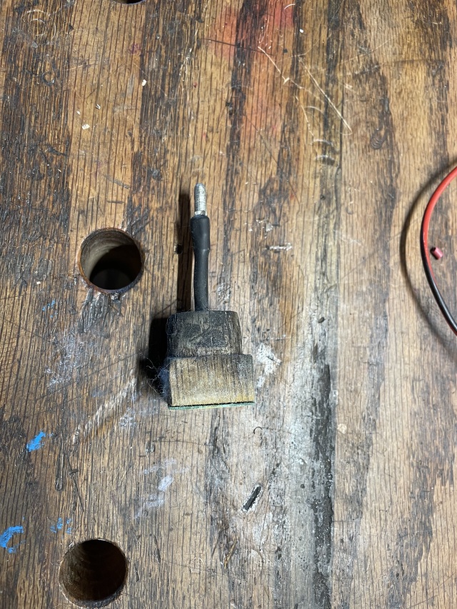
This is how mine is made:
Just a piece of solid copper wire soldered to a thin piece of brass plate. Then I made the wood "handle" and drilled a hole for the wire through the center. Crimped a terminal on the end and used some heat shrink to keep everything together. Then I just cut a piece of felt and wrap the wood and secure it with a cable tie. The brass plate keeps the current distributed evenly over the whole area.
The biggest thing I see though is that your DC voltage is backwards from the way you have the sockets labeled. Your meter is showing +14.7V from the red to the black. If that's the case, you should be clipping the lead from the red socket to the work and applying the lead from the black socket to the pad. It's hard to tell from the last picture but I suspect you are getting all marking and no etching and a backwards DC voltage would explain that. When you apply the pad with DC current you should be able to hear and smell it working and occasionally even see it smoke.