This is a dresser made for a friend years ago when I was first becoming serious about woodworking. It is made out of a matched pair of 10/4 claro walnut slabs. The outer dimensions were given to me as 84" x 32" x 26" deep. It was to contain 16 large drawers and an upper row of four shallow drawers, and a mirror behind to match. All slab fronts were to be live edges. Since I had already done a couple of boxes and some shop furniture, I thought this would be an easy job. After all, a box is a box, right, so what could go wrong?
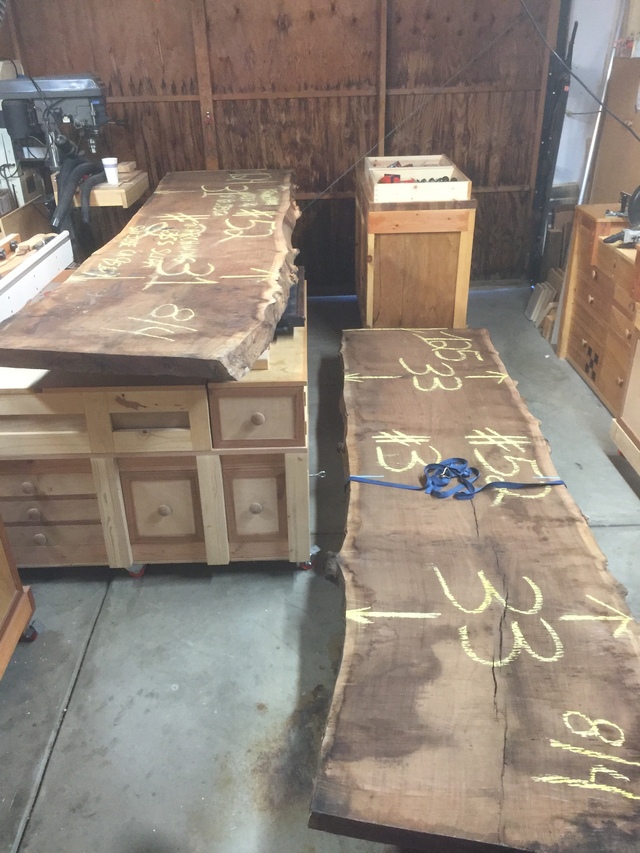
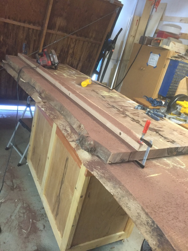
Raw slabs
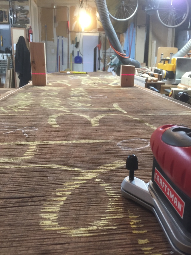
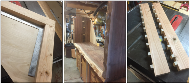
Well, these are heavy; I mean about 300 pounds each. First task: acquire and install an electric hoist in the ceiling. After getting them up on my work bench, the next step was to do some preliminary layout to figure out where to leave the live edges and where to make the cuts. I stretched string on finishing nails to locate the cut lines before chalking them onto the slab. The laser helps figure out where the bow and warp is in order to set it up on the router planer for least stock removal.
Finding the high points
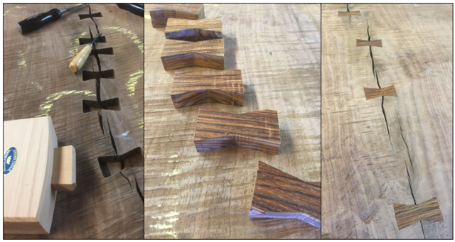
After some quick rough hand plaining, I inserted several butterfly ties across some major cracks and epoxied up the remainder of the cracks.
Dutchmen all in a row
The blanks for the top and sides were cut with a circular saw and a jointed 2x4 for a guide. Since the two rough slabs I bought were book matched, I cut the top from the first slab and the sides from the second slab so that I could later match, or nearly match, the grain in a ‘waterfall’ at the left and right corners of the top.
Roughing out the stock pieces
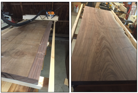
Using levels and lasers, I measured how much and where the slab was bowed so I could locate the center of the bow and properly mount the slab in a router planer box with clamps and wedges. Each slab blank was individually mounted on a router sled frame built from jointed and trued 2 x 4 stock and about 1/8” of material removed to get a flat reference surface on the slab front side. Then, each slab was turned over and taken to a thickness of 1-3/4 inches.
Router Planed Surface
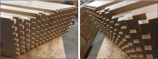
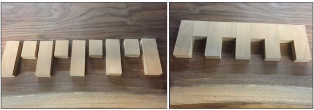
Finally, time to start forming the joinery. I chose to use box finger joints for a number of reasons. They worked on my smaller boxes, they have a lot of glue surface compared to a miter joint, and miter joints were and still are for me difficult to get perfect even on smaller pieces, much less on a pair weighing now 200 pounds and awkward to position in the first place. First, though I needed a finger joint fixture for the router since cutting by hand was out of the question. (These don’t just fit in the vise very easily, so holding a true line with a hand saw was dicey at best.)
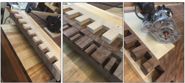
The finger joints were cut using several pattern bits of different lengths, some with top bearings, and others with bottom bearings. All in all, it took about 6 passes to complete the cuts, with hand chisel cleanup of the radius left by the router between the fingers. The matching legs had to have the fingers precisely shifted, of course, to get the edges and grain to match up properly. This was the trickiest part of the build, and if I recall, took several days of careful measure and re-measure before I committed carbide to wood. This is part of the router template I constructed for this operation. Fingers are 1-1/2 wide and about 2" long, leaving room to trim them after assembly.
Finger Joint Router Template
Cutting the finger joints
Gluing up a finger joint between a 100 pound board and a 50 pound board is difficult. Besides the weight, alignment is a challenge. I built a pair of large corner ‘blocks’ from jointed 2 x 4 and plywood, and used these to set the side square to the top. The top was laid upside down on spacers on the bench to allow the side fingers to protrude. I used epoxy to glue the pieces together, one side at a time and clamped the joint using the corner blocks and purpose built cauls that bridged over the protruding fingers. Epoxy makes for a stronger joint and gave me a long set time to get the fit right. The second side was then attached using the same method as the first, but the rails (described next) were dry fitted during glue up to ensure the side-to-side spacing was accurate. The floating tenons were also dry fitted to support the rails.
First Side Glue-up
Both Sides Attached
The bottom of the carcass is not a solid slab for reasons of cost and weight. Instead, a pair of 2 x 6 rails is used, set into the sides with floating tenons. The sides are through tenons. The floating tenons make glue-up much easier, since the rails do not have to be inserted into the sides at the same time the sides are glued to the top. Instead, the walnut floating tenons can be driven in from the outside to connect the rails to the sides later after top to side assembly is complete. The straight live edge cutoff from the back of the top is used for the front rail. The back rail used a length of 4 x 6 birch, also with floating through tenons.
Bottom Rails Attached
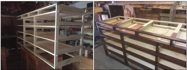
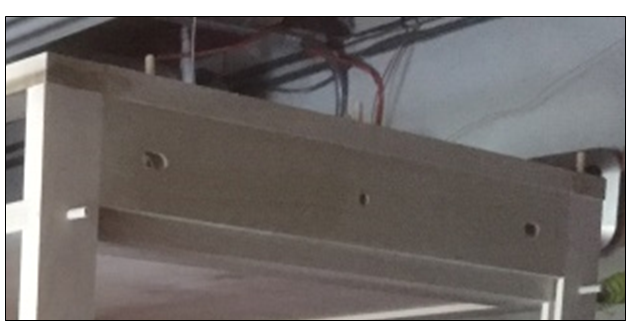
Trying to attach drawer sliders directly to the side slabs would cause several problems. The side slabs will expand and contract with humidity changes, and if pinned to the drawer slides, they will crack, warp, or both. Expansion will also cause to drawer slides to become misaligned, binding the drawers. Similarly, building center supports for the drawer slides into the slab is also problematic. To resolve these issues, I designed an inner frame for the drawers that is suspended inside the slab carcass. Each end of the frame has six attachment points to the slab sides, three on the top and three on the bottom rail, as seen in the following photo of the partially assembled frame. Looking at just the top, it can be seen that the outer two points are horizontal slots, and the middle one is a round hole. The center attachment is fixed to the slab, while the outer two are free to move back and forth as the slab expands or contracts. All three points are held by hex bolts threaded into and E-Z LOC threaded insert in the slab, and the outer two bolts are sleeved with a short length of aluminum tubing to allow easy motion. If you have ever done a breadboard style table top, it works on a similar principle. The scheme is repeated at the bottom of the frame, and again at the other end for a total of 12 attachment points.
The frame parts are pegged and glued together (the pegs are yet to be trimmed flush in the photo), but if I had it to do over again I would use dados and half lap joints instead. The front of the frame is stained to match the claro walnut, although next time I would use solid claro for the front-facing parts. Dust panels ride in dado slots between the rails at each drawer row. Full extension ball bearing sliders are attached to the rails before the frame is placed into the slab carcass and bolted in place. The inside of the slab carcass is also finished with the same varnish and number of coats planned for the outside, following the rule of thumb that both sides of a board should be treated the same.
Drawer Frame Construction Suspension Detail
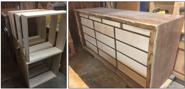
The drawers are assembled from 3/8” thick maple with dovetail joints front and back.
Drawer Sides and Ends on the Bench
Drawers Stacked in Shop and in the Frame
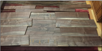
The drawer fronts are made from cut-off parts of the same slab of claro that yielded the top and sides. They are resawn and planed to ¾” thickness. The photo shows them laid out on the floor for pattern matching prior to cutting to size.
Drawer Front Stock Blanks
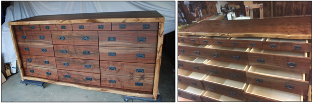
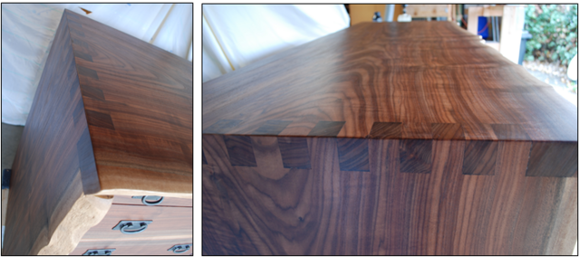
Here is the finished dresser with details of the finished finger joints.
Finished Ready for Shipping
Corner and Top Details
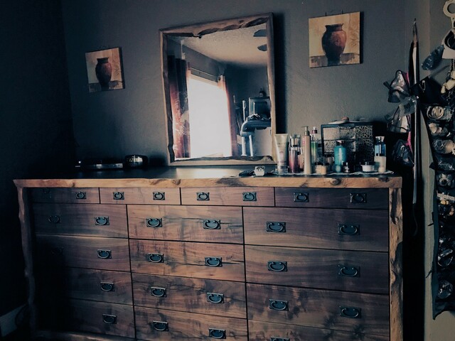
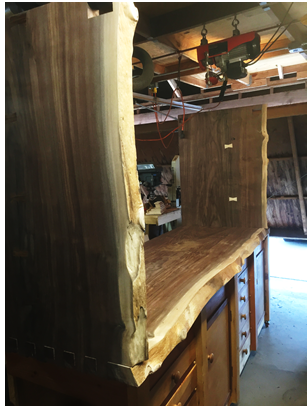
And in its owners residence, with matching mirror attached. The mirror frame was constructed from the live edge remnants of the slabs. Can you tell which side is his and which side is hers?
In Use
Huh? Whadaya mean it ain't "measure once cut twice"?


.png)