Share your craft projects
Make new craft buddies
Ask craft questions
Blog your craft journey

Ron Stewart
926 posts
and
25 followers
in about 3 years
in about 3 years
More from Ron Stewart
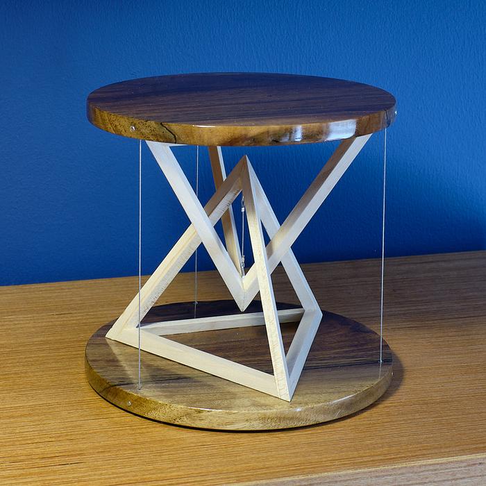
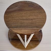
Mini Tetrahedral Tensegrity Table
I've been fascinated by tensegrity structures, particularly tables, since I first encountered them on the web. At first glance, they look impossible, but they make sense after you study them for awhile. In a nutshell, tensegrity tables are composed of two structural assemblies. The top assembly hangs off the bottom assembly by a wire, and wires connecting the outer edges of the two keep the top assembly from tipping over. If the top starts to tip in one direction, the wires on the opposite side stabilize it. As a result, it can't tip over in any direction.
Tensegrity stands for "tensional integrity." I won't try to explain the concept further here, but the YouTube video Tensegrity Explained does a good job of describing it. (It also shows a commercially available table kit with a clever mechanism for attaching and adjusting the support wires. I got the idea of using nails to hold the support wires in my table from that video.)
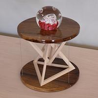
We don't need any more full-size tables right now, so I decided to build a miniature one. It serves no useful purpose, but it looks interesting and was a challenging project, incorporating elements of geometry, model building (because of some very small parts and joints), and jewelry making (beading wire and crimping) in addition to traditional woodworking.
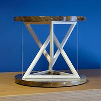
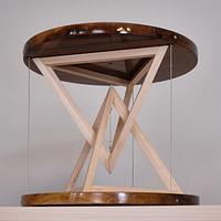
My table is about six inches wide and tall. The top and base disks are 3/8" thick walnut, finished with gloss Arm-R-Seal poly over amber shellac. The two tetrahedrons (which I'll just call pyramids) are made of maple, finished with matte General Finishes water-based poly. The faces of the pyramid segments are 1/4" wide.
The pyramids are the centerpiece of the table, both literally and figuratively. I chose to use them because they're more interesting to me than the flat L-shapes, triangles, or circles I see in the centers of most tensegrity tables. I was inspired by another YouTube video that uses tetrahedrons. I didn't understand everything the guy did in his video, so I modeled my pyramids from scratch and used a different method to build them.
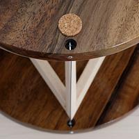
One of my goals for this project was making the structure look light and delicate. Part of that involved keeping the disks and pyramid segments thin. The other part was keeping the wires and their connections as unobtrusive as possible. (I didn't want any noticeable eye bolts, for example.) The beading wire is very thin--0.024", which is about 1/40" or 0.6 mm. Loops on the ends of the wires are secured by crimp tubes that are only 2 mm tall and 2 mm in diameter (before crimping); they're tiny.
The loops on the outer wires are pinned inside circular pockets in the disks' undersides by 16-gauge brad nails. The pockets hide the wire loops and most of the crimp tubes. The nails are perpendicular to the disks' edges, with exposed heads. I like the look of the exposed nail heads, and they have one practical benefit. Theoretically, I could remove the nails and rewire the entire table if necessary for some reason.
I wasn't quite as successful at hiding the connections for the wire connecting the two pyramids. The crimp tubes are visible, as are the J-hooks they connect to, but they're not too objectionable.
For anyone interested in the actual design and construction process, I posted a very detailed blog series. The SketchUp model is also available on the 3D Warehouse.
Thanks for looking!
7 Comments
I’ve always thought those tables are awesome. I like the idea of a small one! I wonder if my beer would stay put on top of it??? ?
Ryan/// ~sigh~ I blew up another bowl. Moke told me "I made the inside bigger than the outside".
Thanks, Ryan! It would easily hold a beer. It would wobble a bit, but I think it'd be safe. :-)
very cool ron.ive always thought of making one myself.i wonder how big you could go with this technique. i think it would make a great plant stand ?
working with my hands is a joy,it gives me a sense of fulfillment,somthing so many seek and so few find.-SAM MALOOF.
Thanks, pottz! A bigger one would make a fine plant stand. I think the weigh-bearing capacity depends on what you use for the "wires." I've seen people use rope and chain. If I were building something bigger, I'd look at thicker picture hanger wire.
BTW, it's good to see you here. I read what I think was your last LJ post, and I can't believe it got you banned.
BTW, it's good to see you here. I read what I think was your last LJ post, and I can't believe it got you banned.
thanks ron. after i had vented and said my peace i knew she was gonna ban me,weve had a long running disagreement as to what i say violates the rules.of course she has the power to win any argument-lol. ill be back after dec 7, i guess ? sure am lovin it here though. glad to see you too.
working with my hands is a joy,it gives me a sense of fulfillment,somthing so many seek and so few find.-SAM MALOOF.
I, too, find these tables fascinating.
Thanks for reminding me about them ..
And yours??impressive!
Thanks for reminding me about them ..
And yours??impressive!
JAGO - just a grandma’s opinion
Thanks, MsDebbieP!
And pottz, I’m glad to hear you are just in “time out” at LJ, instead of perma-banned.
And pottz, I’m glad to hear you are just in “time out” at LJ, instead of perma-banned.


