Share your craft projects
Make new craft buddies
Ask craft questions
Blog your craft journey

LIttleBlackDuck
5504 posts
and
55 followers
in over 3 years
in over 3 years
More from LIttleBlackDuck
Large Wheel kerfing jig for T&J (any) models
Boys and Girls,
As we all now know about the loss of content by many members who either no longer venture to the Lumberjocks domain or have managed to get canned, I got concerned about being categiorized as a gopher for that ratbag radical Pottzy (at least that's what he's called there).
Consequently I have decided to put a greater effort to bring across a few more of my LJ past projects before they too get vaporised.
This is one of my favourites and I have probably distributed around a dozen copies of it worldwide, for the princely cost of P&H… until international shipping costs put a dampener on the enthusiasm of all concerned.
It was one of my early post on Dec 4, 2016… hell I wasn’t even old enough to shave back then and the “Boys and Girls” haven’t been heard of..
Anyone interested in my links, please ignore the ones in the "migrated text" and use the following….
3DW Model
1. Tablesaw Version (Original Pin Indexer),
2. Router/Foredom Version (Pin Indexer),
Videos:
1. Wheel Kerfing jig 9 Incher Part1
2. Wheel Kerfing jig 9 Incher Part 2 follow up
3. Wheel Kefing Jig, Modification #02
Anyone interested in making wooden gears (in general), here is a good starting point
------------------------------------------------- ooo000OOO000ooo --------------------------------------------------
Hi all. I have been debating whether I should publishing this article regarding my "Wheel kerfing jig" for T&J destined wheels
because the jig is primarily laser cut with only the indexing pin created using conventional woodworking techniques.
"Laser cut???" you say… well join in the chorus… as not too many people have lasers or even access to one, but with the growing popularity of CNCs and their acceptance in the woodworking community, I now probably have 2 or 3 more interested people added to my captivated audience.
I finally decided to publish this article for 2 reasons:
- I made a video of using the jig that runs for far too many miles to keep viewers interested without a lot of toilet breaks and this may alleviate that burden and could use some further explanation. Here is the link to the video (suggest you grab a slab of beer and a pizza first).
- While you probably have a "snowball in hell" attitude towards such a build, I'm hoping you may get some sort of "inspiration" to use parts of my presentation/ideas in some other independent woodworking ventures.
- Hmmm? I can't count…
The jigs suggested by T&J are boards with dowels clamped to a mitre gauge and slanted (or straight) across a table saw,
or a router table,
I have seen many great jig designs and innovative ideas, however, they all seemed to get bogged down with "advancement to the next index" and the "lock down" process while making the cut.
My intention was to devise an indexing/locking mechanism and then building a jig around that which was a complete rrrs about logic and in-keeping with this authors "mental orientation". This exercise was more of a challenge rather than a requirement, as I had become quite familiar with the production of simple dedicated wheel kerfing jigs for each style of wheels as per the T&J instructions.
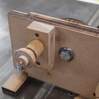
After designing a spring loaded locking/indexing pin mechanism I then proceeded to designed a base to hold the wheel.
I used a far too heavy spring in the 1st. pin mechanism I made. As it took too much of an effort to pull it out and fearing early destruction, I made another one with a much lighter spring.
As I progressed with the design, it kept gravitating to a modular MDF build suited for laser cutting.
During solution contemplation, I quickly realised that it was impractical to have the indexing wheel in line with the wheel to be cut as the indexer would need to be smaller and that would make the indexing holes impractical.
So I came upon this bright idea of gears and gearing ratios.
Unfortunately the solution was totally out of whack with my initial draft. The first design was totally screwed up as I planned on equating the number of gear's teeth with the number of indices required.
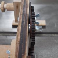
I considered a 2:1 ratio but my logic was reversed as I had the small gear attached to the wheel with the larger gear incorporating the indexer.
This gave me a 1:2 ratio with the kerfs at every 2nd. location… DOH! I thought that I could rotate the wheel ½ a kerf and then re do but after many misalignments that idea was scrapped.
This concept required a relocatable indexer, hence the elongated pin holes (rather than just plain circles) in the index wheel that just never got update.
The only problem is that a "draft" in timber is not like paper. After making the component it was a bit difficult to erase misplaced holes and I had to redesign and re cut.
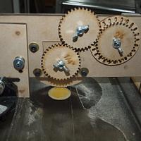
I found that such a large index wheel was an overkill and thought that to separate the two geared components and compensate for a smaller index wheel, I will need to introduce a 3rd gear… This was designed around the location of the index pin mechanism. I never considered moving the index pin… that would have been far too easy. This was already over-engineered… why stop here.
Combined with frustration and many mental blocks I somehow thought about using bearings in the jig to facilitate the introduction of this new gear.
I kept forgetting that one of the key features of SketchUp was simulation and unfortunately the laser cutting made minor modifications too easy and rather that re-evaluate the jig and do a total redesign I made quick "adjust to fit" modifications using SketchUp followed by quicker laser re-cuts.
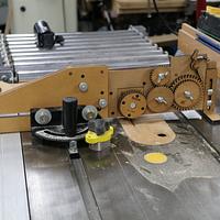
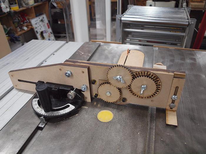
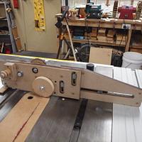
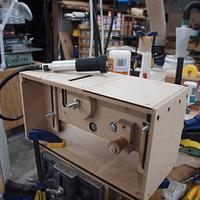
The following is the components of the jig's components in the "table saw" mode.

Two examples of wheels created using different indexing wheels.
After completing the jig and observing some other jig designers using routers, I considered extending its functionality accordingly.
I designed what I affectionately refer to as the "Foredom configuration". This configuration has the geared base with indexer mounted into a "router kerfing table" type setup. You can then use a Foredom, Dremel, trimmer or router with the appropriate following template to cut the kerf.

The kerf is controlled by following designed tracks using template followers. You can design any pattern you like and this can permit non-linear kerfs to be cut as opposed to the straight kerfs on a table saw.
To cut different shaped kerfs all you need to do is replace a template that is located by 4 dowels on the "router kerfing table".
I prefer to use a Foredom as it is very manoeuvrable, can be operated by one hand and with the appropriate hand-piece will accept ¼" router bits. To permit ease of use of a Foredom tool I designed a 3D printed jig to hold the Foredom and permit its use with the following template. While the base of this 3D printed jig is relatively small it is large enough to provide stability.
I have created another long winded video describing the features of the SketchUp model here. Please note that it is not a how to but what was created and why.
The "laser cut" parts would need to be separated for CNC cutting. How to CNC? Je ne sais pas… RTFM.
PS.
The jig has not been used for angled kerfs nor "production" tested in the Foredom configuration
Anyone interested in making wooden gears (in general), here is a good starting point .
#########################################################################################
Late Addition:
To appease the need for "Bigger Boys' Toys" the jig had to be reengineered and can now take up to 9" wheels.
To accommodate this, the gear layout had to be modified and an additional "control" gear was added.
Fortunately after the changes were made in SketchUp, the transition to the workshop and reality was purely academic. In layman's terms… the laser got it right first time.
I created a new video showing it in action the larger wheel, however, I cocked it up as I didn't apply constant pressure in a lateral position on the driving gear wheel. To demonstrate what incorrect practices will result in I left the video in to serve as a bad example and re-shot it here to demonstrate what I should have done.
If your first cut is too short... Take the second cut from the longer end... LBD
5 Comments
like the other imressive
Ron
If I was to build all that, it'd be quicker for me to just grow a small tree inside a tire mold!
Plenty cool!
Plenty cool!
Neat build!
Ryan/// ~sigh~ I blew up another bowl. Moke told me "I made the inside bigger than the outside".
Very Cool Duckie!!
Mike
This jig is a work genius
Life’s Good, Enjoy Each New Day’s Blessings


