Share your craft projects
Make new craft buddies
Ask craft questions
Blog your craft journey
Ron Stewart
954 posts
and
24 followers
in over 3 years
in over 3 years
Mini Tetrahedral Tensegrity Table Details #10: Tensioning the Wires and Completing the Project
This is
part 10
in a
10 part
series:
Mini Tetrahedral Tensegrity Table Details
...
-
Finishing the Disks and Attaching the Pyramids
-
Tensioning the Wires and Completing the Project
...
- Finishing the Disks and Attaching the Pyramids
- Tensioning the Wires and Completing the Project
At this point, the moment of truth had arrived. It was time to attach the tensioning wires and hope they didn't tear the pyramids apart or result in a wobbly table.
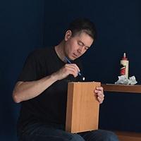
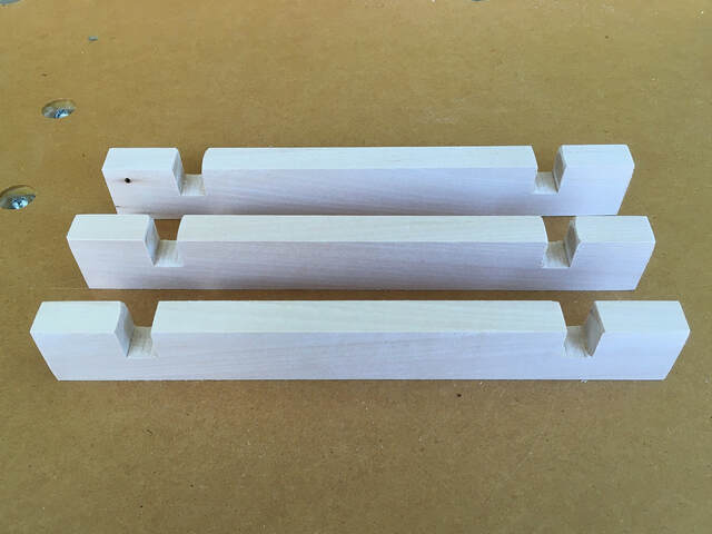
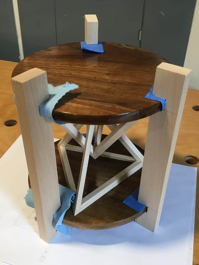
I decided the best way to proceed was to create three support brackets that would hold the disks at the right distance apart. (That was 5", which I had determined by holding the disks at different distances until one seemed right.) The brackets were just 1/2" thick slats of wood with slots to hold the disks.
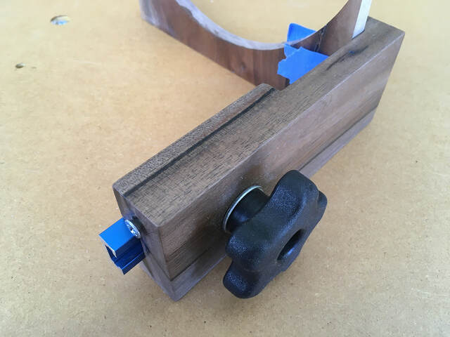
I wanted the brackets to hold the disks firmly without marring the finish, which had not cured. I wrapped a doubled-over length of painter's tape around a walnut scrap and used my kerfmaker (which I made from the same walnut board some time back) to record the required slots' width. The resulting slots would be as wide as the scrap was thick, plus four thicknesses of the tape.
I decided the best way to proceed was to create three support brackets that would hold the disks at the right distance apart. (That was 5", which I had determined by holding the disks at different distances until one seemed right.) The brackets were just 1/2" thick slats of wood with slots to hold the disks.
I wanted the brackets to hold the disks firmly without marring the finish, which had not cured. I wrapped a doubled-over length of painter's tape around a walnut scrap and used my kerfmaker (which I made from the same walnut board some time back) to record the required slots' width. The resulting slots would be as wide as the scrap was thick, plus four thicknesses of the tape.
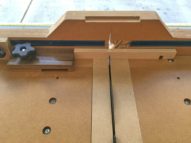
The kerfmaker has an adjustment screw. The distance from the head of this screw to the kerfmaker's body is the same as the width of the teeth on my table saw's blade. A length of T-track protrudes from the body the same distance as the thickness of the desired slot.
To use the kerfmaker, I positioned the screw against a crosscut sled stop block and made one cut.
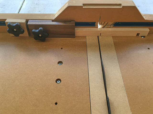
Then I rotated the kerfmaker so the protruding T-track touched the stop block (which I did not move) and made the second cut.
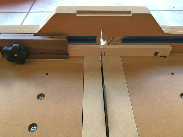
Then I just removed the material between the two cuts, and the slot was the correct width. I didn't have to measure or mark anything except the inner edges of the slots.
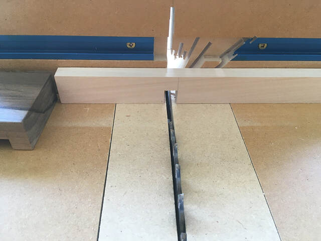
I cut all three brackets at the same time so they were as close to identical as possible. Then I used sandpaper to bevel the inner edges of the slots.
If you don't have a kerfmaker, I highly recommend building one. Mine is based on this video . It's the simplest design I've run across, and it's a huge time saver.
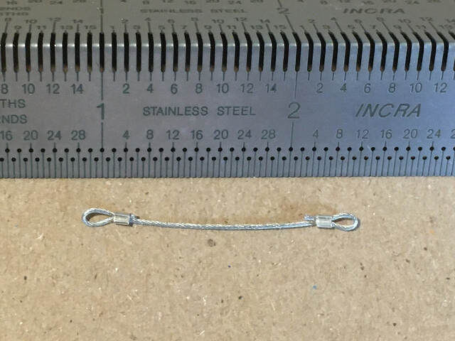
Now I was almost ready to wire. First, I needed to confirm that a looped end of wire, plus its crimp tube, would fit through the holes in the bottom disk. I measured the width of a crimped wire/tube: 0.059".
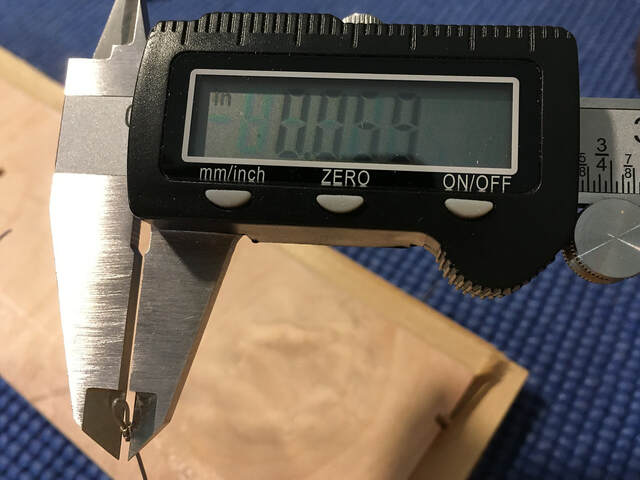
It should have fit in a 1/16" (0.0625") hole, but it was a bit snug (probably from poly residue), so I enlarged the holes with a 5/64" (0.078") drill bit to provide some wiggle room.
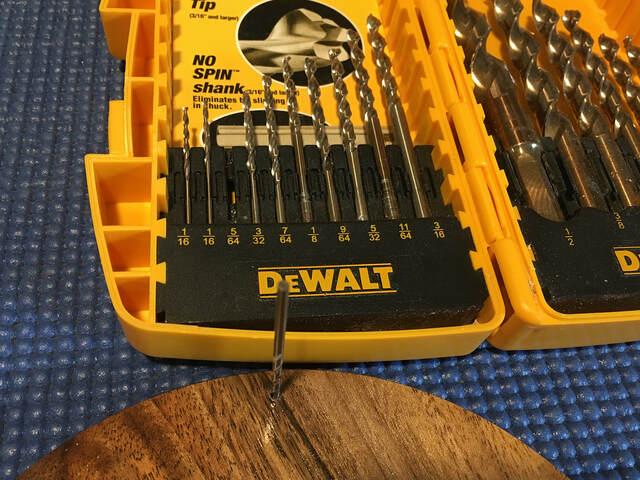
The loop and crimp tube now slid through the hole easily.
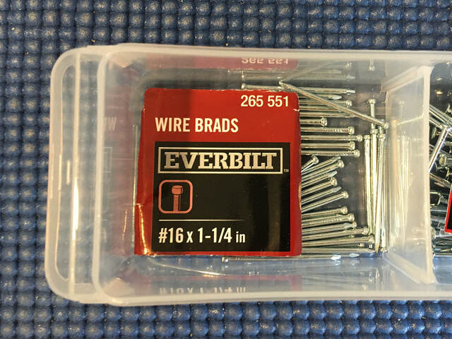
Now I was really ready to wire, starting with the all-important center wire. I crimped one end, making the loop as small as possible by using a 16-gauge brad as a guide.
I slid another crimp tube over the other end of the wire and formed a loose (uncrimped) loop. I slipped the crimped loop around the top pyramid's J-hook and then moved the support brackets in place.
It took some patience and maneuvering with needle nose pliers, but I was finally able to slip the loose loop over the bottom pyramid's J-hook, then carefully pull the wire taut. With the wire held taut, I pushed the loose crimp tube closer to the bottom hook and squeezed it slightly to hold it in place. Then I removed the support brackets and center wire and fully crimped and trimmed the temporary loop.
In preparation for adding the outer support wires, I slipped the center wire back over the two pyramid's J-hooks (which required a lot more patience), then put the support brackets back on. I plucked the center wire to make sure it was still taut.
Now I was ready to attach the outer wires. I started by cutting three oversized lengths and fully crimping one end of each and setting aside the brad nails that would hold the wires in place.
Adding the first two outer wires was quite easy. For each, I followed this procedure:
- Slip the crimped loop over a nail and slide the nail into the top disk.
- Slide another nail into the bottom disk, leaving about 1/8" protruding.
- Add a crimp ring and loose loop around the uncrimped wire end.
- Slip the loose loop over the bottom nail.
- Use pliers to pull the wire taut and slide the crimp ring snugly against the bottom nail.
- Slightly compress the crimp tube to hold it in place.
- Remove the nails and wire.
- Finish crimping and trimming the bottom loop.
- Insert one crimped loop through the hole in the bottom disk, and insert a nail through the loop.
- Using pliers, hold the top loop inside its pocket and slide a nail through it.
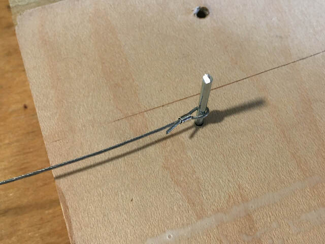
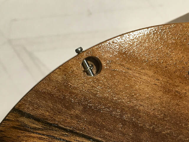
Here's a photo of one of the bottom wires. You can just see the loop around the nail.
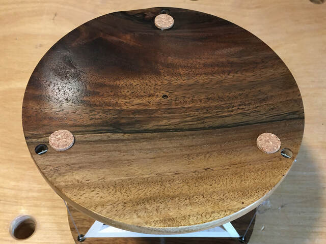
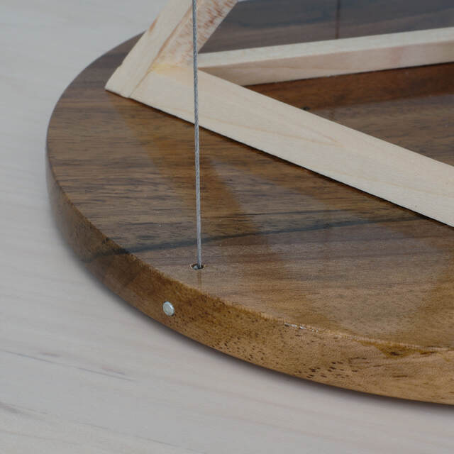
Here's a photo of the bottom disk from above. The crimp tube is buried in the "ceiling" of the disk and is essentially invisible.
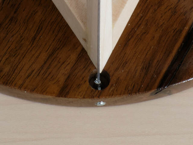
The crimp tubes for the top wires sit almost fully inside their pockets.
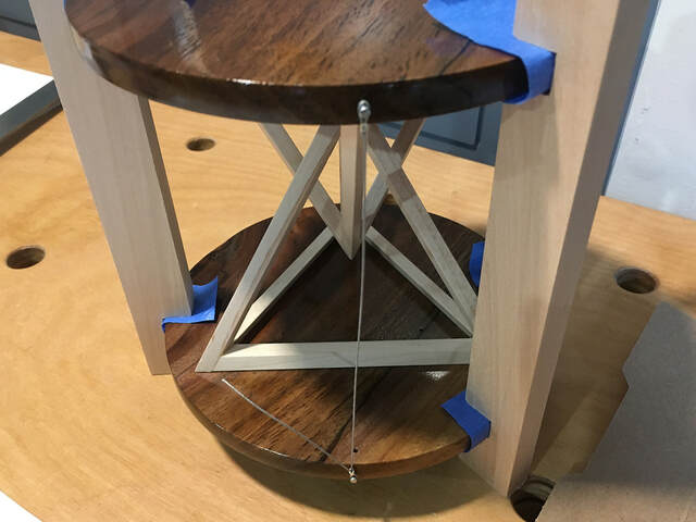
I decided not to leave the support brackets in place for the final wire. (With the brackets in place, I didn't really know if the first two wires were tensioned properly.) I had to be very careful to support the incomplete table at all times, because it was very unstable. I used the same procedure to set the last wire's length (I could feel when it was taut enough) and attach it.
I felt a great sense of relief. The table was nice and stable, and I didn't have to re-tension any of the wires.
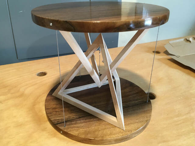
All I had to do was use a nail set to tap the nail heads flush with the edges of the disks, add some cork disks to the bottom, and the project was complete.