With the CNC cart completed, I could get back to working on the flip cart. I had purposely delayed work on it because I was struggling with part of its design, which was the idea of having to outboard the casters - mounting them on the outside of the main box. The TLDR reason I thought that would be necessary was ultimately to provide sufficient lateral stability. With the tallest tool at 21" max height, a desired bed height for both tools at 34", the back bracing (the primary lateral support) would end up being too narrow (in height) for my comfort if the casters were mounted on the bottom of the box as is usual.
Hence, I would build the box to sit close to the ground (1/2") and mount the casters externally on some platforms at the corners. I had worked out how to do it, but I just didn't like the idea of making the footprint of an already largish cart (25-1/2" x 28-1/2") even larger by adding external casters.
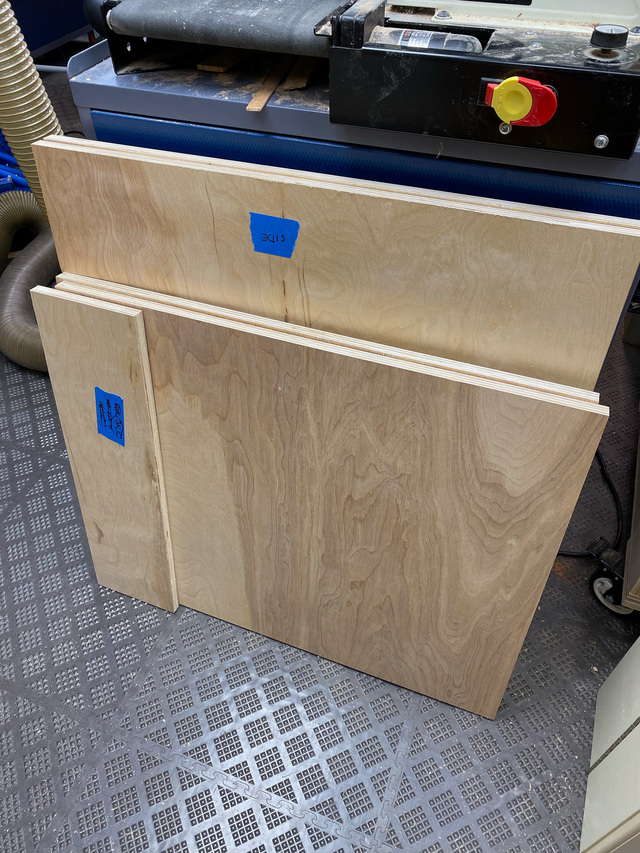
I decided that it would be prudent to test the stability of the cart with the planned design before deciding to change anything. So I started getting the pieces cut out.
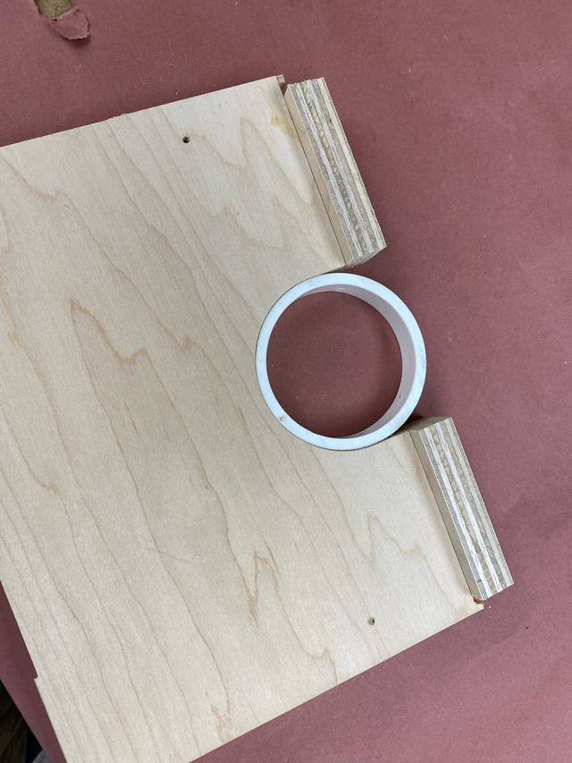
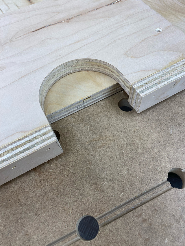
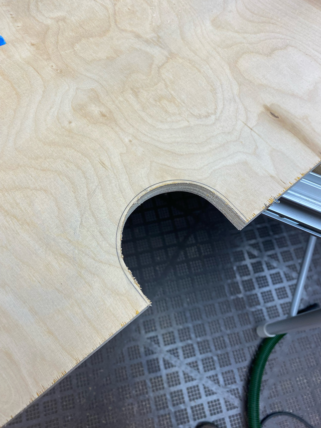
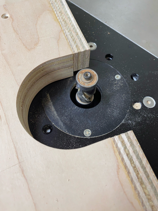
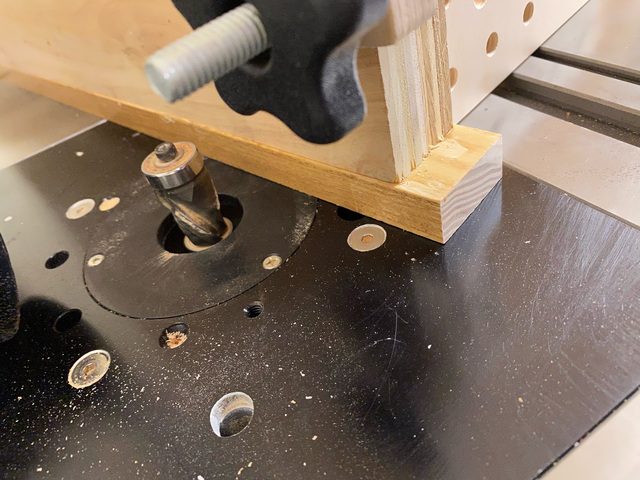
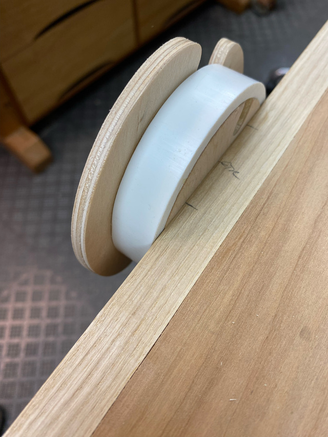
For the hub cradles in the sides, I made a quick router jig. I cut the bulk out with the jigsaw. Flush trimmed on the router table.
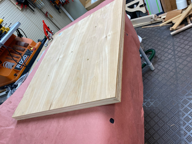
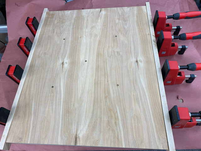
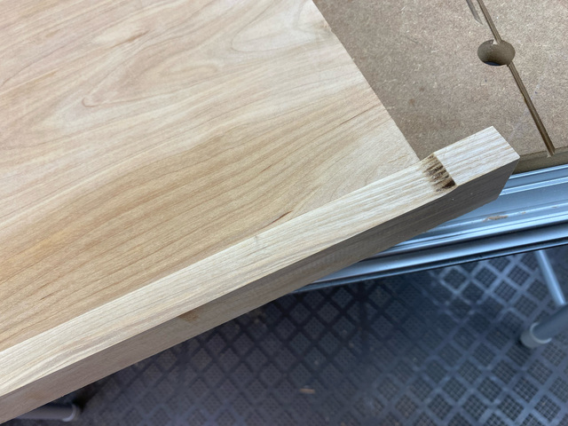
The platform is two pieces of 3/4" plywood glued together. I had intended to leave the long edges bare plywood, but since one face had a damaged edge, I trimmed it down and glued-on some of the same salvaged ash that I'll use for stops on the short edges later.
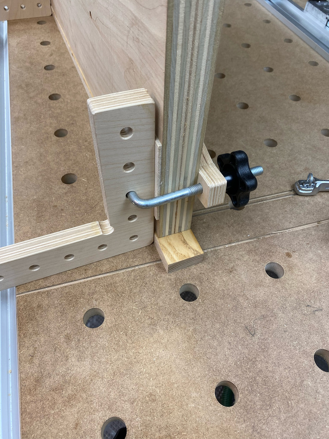
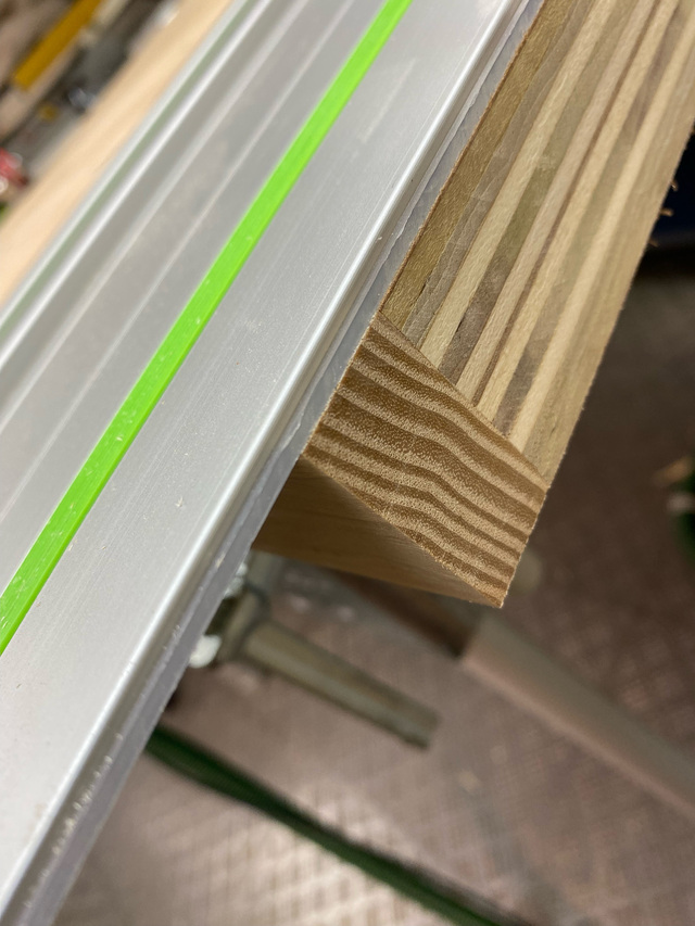
Flush trimming the edging was a bit cumbersome. I didn't want to take the time to setup a tall fence, so I just used some right angle clamping fixtures to help keep the platform perfectly vertical on the router table. It probably would have been a bit easier to do this with a hand router. But it worked. I then trimmed-off the excess on the short edges and will add the stops at a later time.
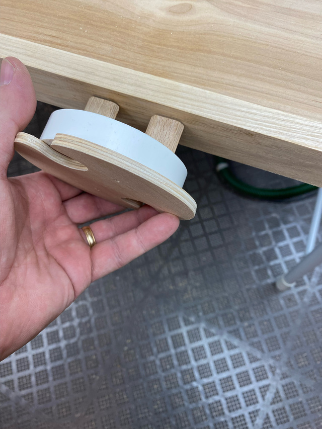
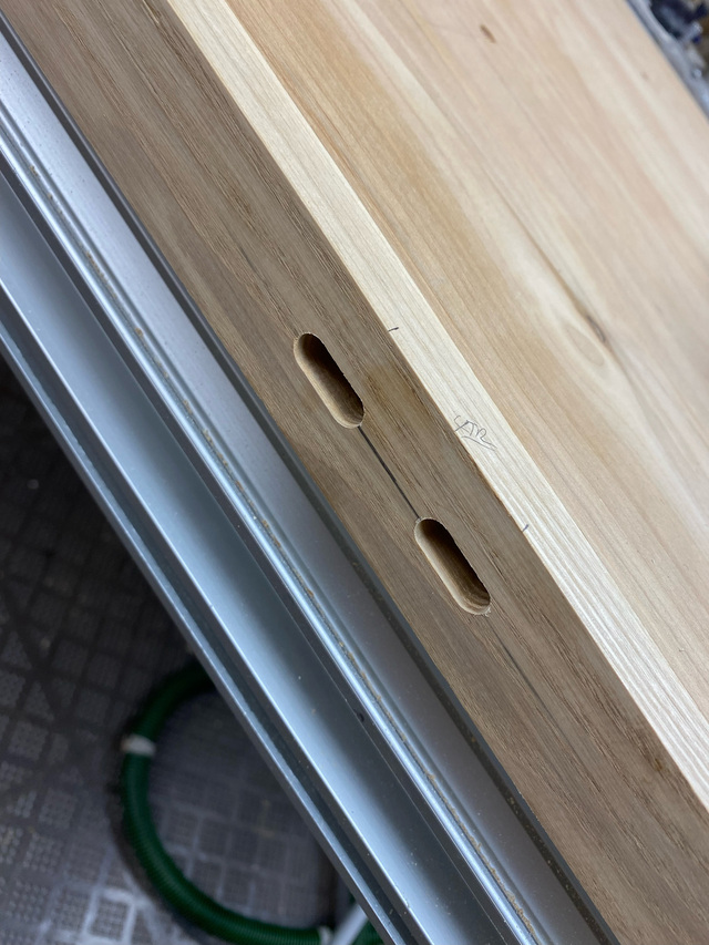
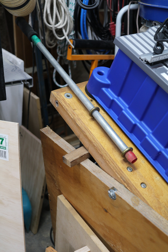
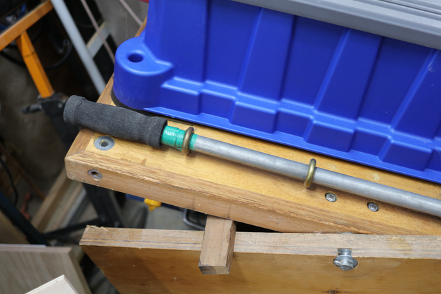
Each hub attaches to the platform with a pair of 8mm dominos.
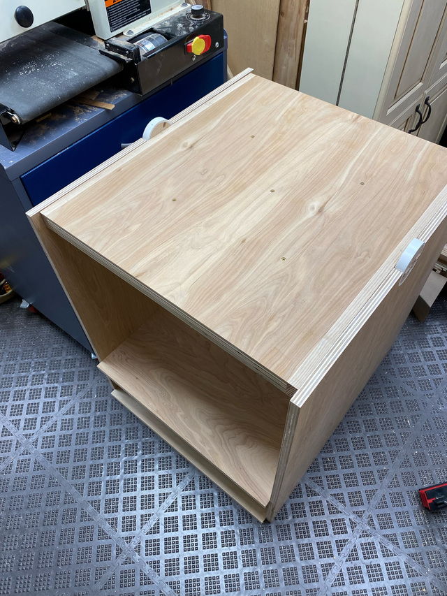
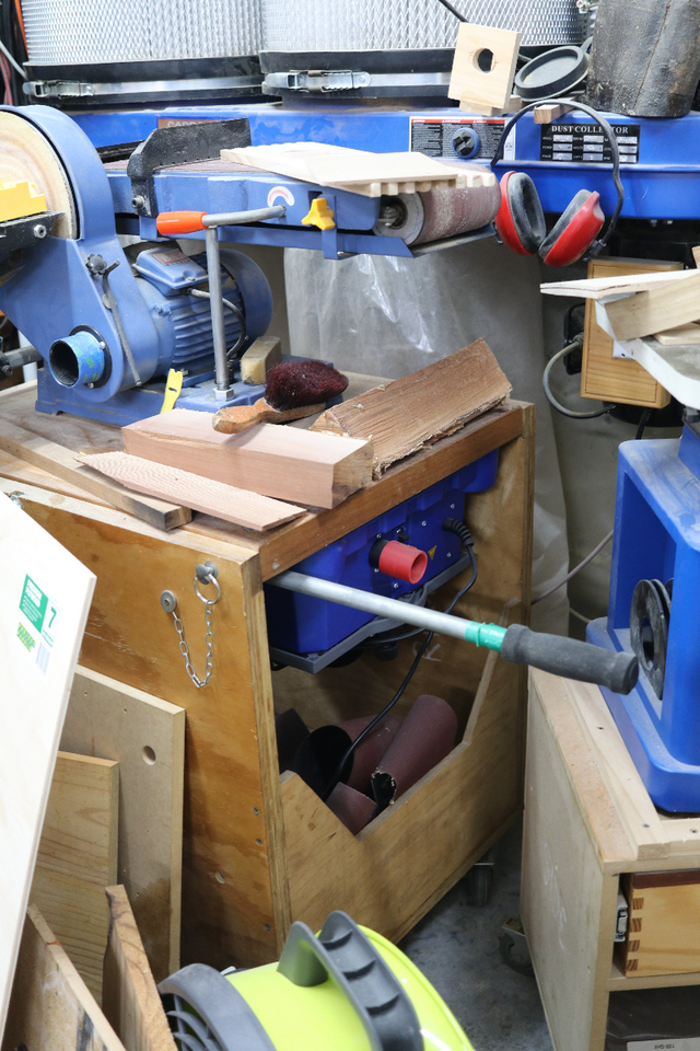
I used only pocket hole screws to temporarily assemble the cart. Once I get a sense of its stability with a tool on it, I'll disassemble it all to make some design tweaks before reassembling with glue and screws. (The shelf and bottom panels are too long anyway.)
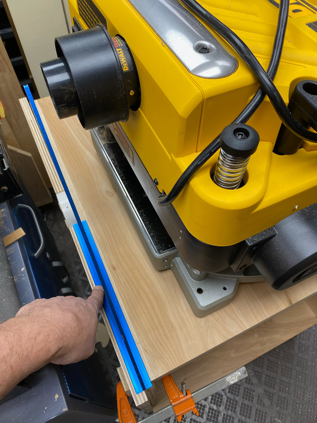
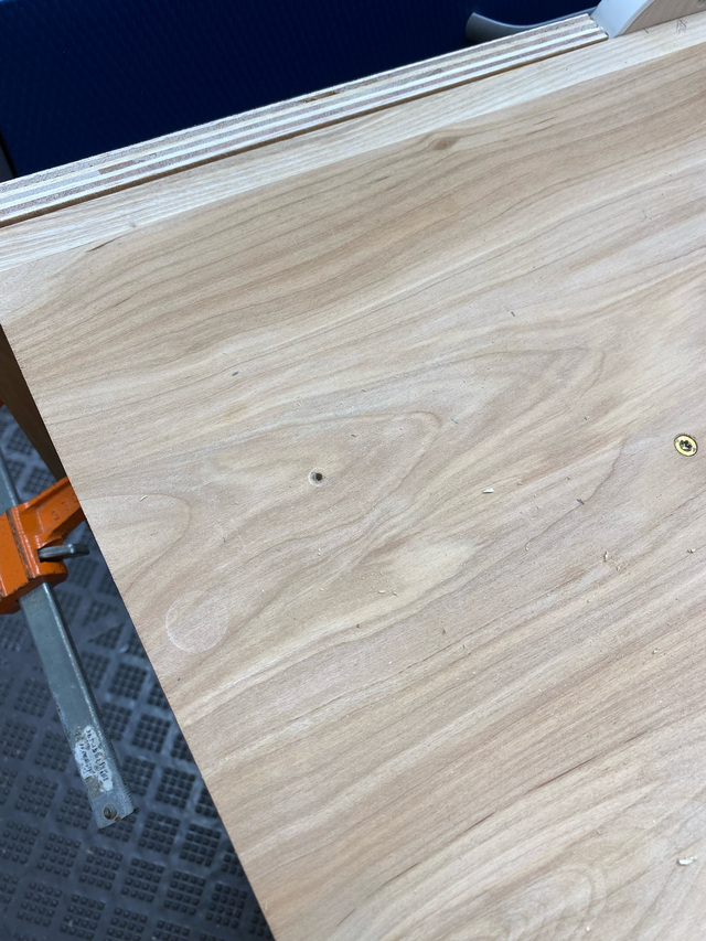
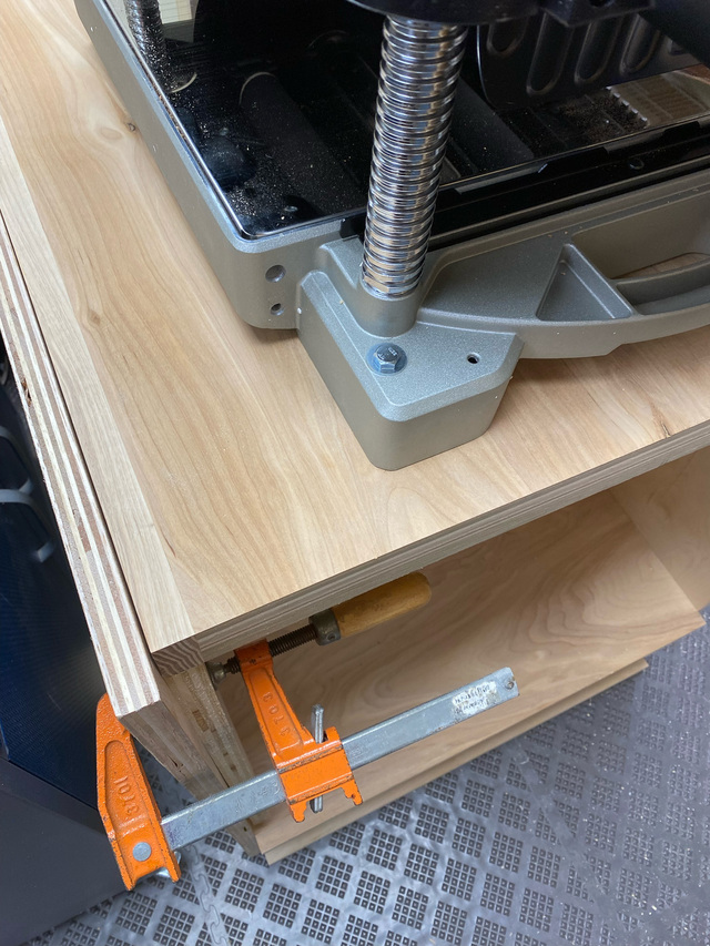
With some temporary stops to keep the platform from rotating, I set the planer on top and got it into position for mounting, and marked the bolt hole locations. Here I'm checking to make sure the dust collection fitting will clear.
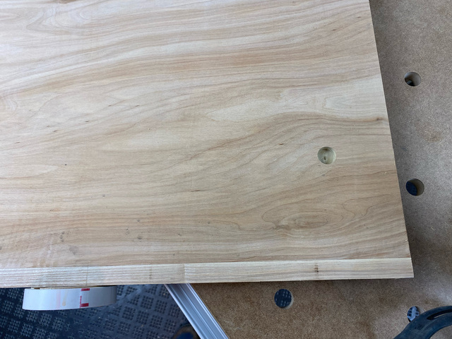
With small pilot holes through the top, I could remove the platform and drill the counterbore and bolt holes from the underside.
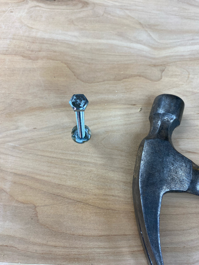
With the bolt installed backwards in the T-nut, I could tap on the bolt to seat it.
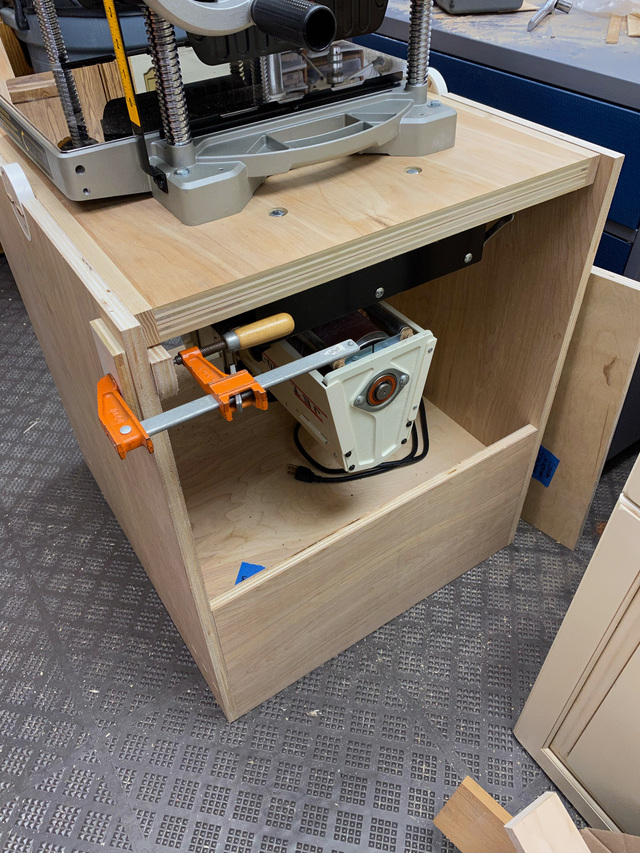
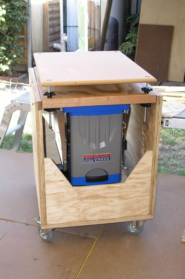
With all 4 T-nuts installed, I could temporarily mount the planer to see how the platform rotates.
Without the drum sander to counterbalance, it takes some care to flip the planer, but the rotation is smooth and even with just the pocket hole screws, the cart feels pretty stable. After noodling on it for a while, I'm going to scrap the external caster plan and go with inset casters. More on that in an upcoming post.
Thanks, Splinter. I'm going to temporarily mount the drum sander this evening and give it another spin. The additional surface area of the hub in the cradle (compared to the black pipe method) seems to add friction, which I think will be good with the inertia of all that mass. It's not hard to overcome the friction, but it might keep the rotation more controllable.
Thanks, Eric. I oriented the feed direction along the rotation axis so that I could build in collapsible infeed/outfeed stands that I can leave deployed when rotating the tools. That’s the plan anyway.
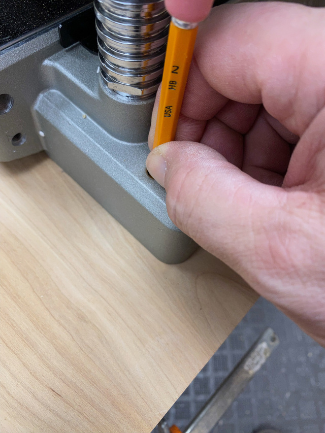
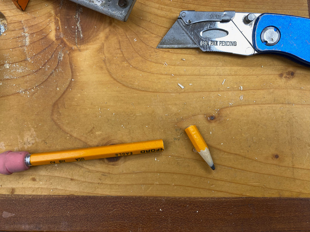
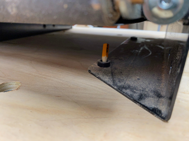
I got the drum sander mounted on the platform last night. It has captive nuts in its base for mounting, and a pencil was sacrificed to mark their locations.
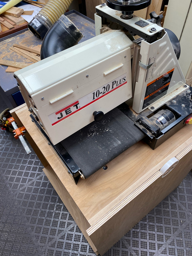
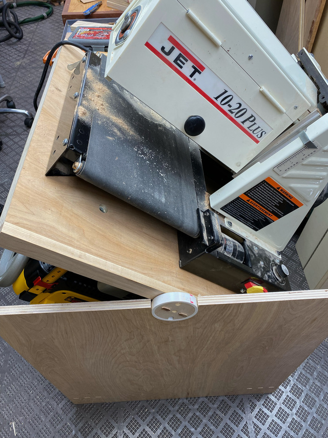
The sander in the stowed position. This shows the back bracing piece. Because the platform rotation will be limited to 180 deg, the shorter tool (planer) will be rotated on this back side so I can maximize the height of that lateral support. Part of this exercise is to see how much room there is to extend that piece upwards. With the planer head raised higher than I'll normally need, I found that I can raise that back edge about 1.5" more and I can change the shape of the back piece to create built-in gussets where it meets the sides.
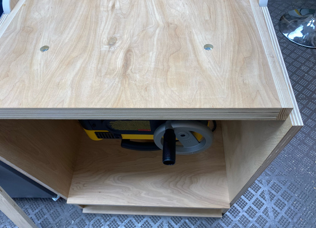
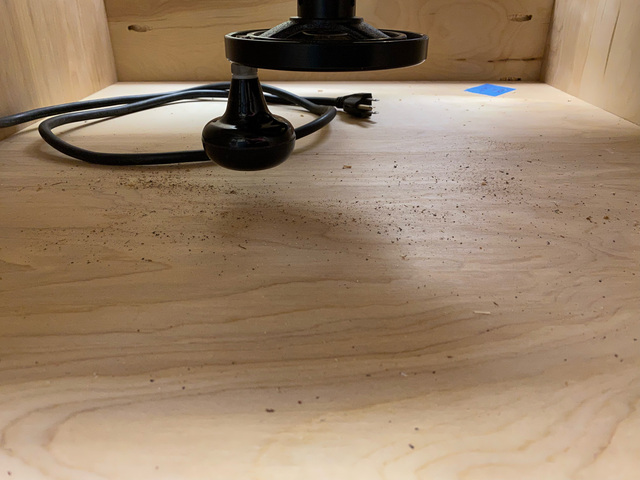
Here you can see how the knob on the drum sander dictates the height of the shelf. I probably have about a 5/8" or 3/4" gap there.
And because the drum sander is more heavily weighted towards its right side (the motor), this is the equilibrium point with the heavier planer on the bottom. I could shift the planer, but that would cause its handle to protrude out of the side. I could shift the sander about 1-3/8" to move its motor towards the center, but I'm not sure that will help much. It's not ideal, but even with the tools unbalanced, it's easier to rotate with both tools installed than with only one.
How stable is it laterally? With "thinish" sides, I had issues and had to fortify mine using a profiled front, just 2bsure, 2bsure. Though that bottom shelf looks like it may do the trick.
If your first cut is too short... Take the second cut from the longer end... LBD
LBD - I do plan a similar lateral brace that extends upwards at each end. The planer will enter/exit on that side, so I'll be matching the brace profile to that tool.
to assist in levering the revolving lid... initially one flip was used as an adjustable outfeed table for several machines (as required), Currently the two machines are way out of balance... the Foreman is all plastic compared to my belt/disc sander. Not pretty but was a must for flipping.
If your first cut is too short... Take the second cut from the longer end... LBD