After unloading a bin full of woodworking Jigs I realised I may need an Adjustable Jig. looking through my stock I found enough timber and hardware to build one.
the bolt head track was made by ripping thin pieces from a additional piece sawing a 10 mm recess and then gluing on the thin retaining strip
then ripping a 8 mm opening for the tee bolts
next came the task of holesawing 10x 50 mm holes in hardwood I used the LBD method of saw kerf sawdust removal.
Note;- (if by some chance you believe you have a entitlement to the method please acknowledge it and appropriate recognition can be afforded too)
Process As I wasn't making wooden toys like Crowies so the exit holes were drilled in the inside of the openings, or "wheels". They were not scrapped though as they were needed to be "mooned" and then glued back in. Paying attention to the grain orientation. one piece of timber had an unacceptable twist in it so I made smaller pieces to have a large jig and a smaller more manageable jig. Speaking of jigs I used offcuts to fashion a boring jig for the ends
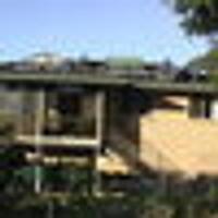
Assembly With that all complete it was time to test out the results of my two days work.
It seemed to work well and I was pleased with it
Just a test run on some scrap material.
The router setup
Obviously with an enclosed profile a plunge router is needed. A trimmer could be used if remaining material is to be removed. If a top bearing is fitted to the router bit no additional spacer is required Dimensions:- The larger one has 900 mm long sections The smaller as you can see has a few options from about 250 mm to 400 mm I finished them with orange Oil.
I might decide to retro profile a few kitchen cupboard doors and add some bling!
Cool RC... however, I would be concerned about the strength of those timber tracks... especially when you have the option of over tightening with a spanner (though pulling against a supported wood surface give some grace)... wood against wood may provide enough friction to get away with appliable pressure using knurled knobs (if you can find them)... well, that was my theory when I opted for aluminium t-tracks. Your "mooning" is a neat touch.
Great to see the MFT style in use... which as an outsider has just set me off brain storming... the high profile of those hold down clamps can be obtrusive when using a full faced router loaded with a following template (may bluff with a smaller trimmer and/or flush bearings if possible) and have always concerned me in the past... while they may be carefully placed not to obstruct the router/trimmer, those high shafts can rip the hairs out of the armpits.... got me thinking and immediately off to the workshop.... back about 25 minutes later with a few happy snaps... using an existing ji,g whose hole patterns could be imitated in this type of setup. Something like one of these 3 options I quickly came up with, The one on the left could still jeapardise the router (but save the 'pits) and would be a bugga to screw the top arm down, the one on the right would still be a bugga screwing down through the hole, if not attached on the bench edge, however, the middle seems the Goldilocks. Top view... that insert if 8mm threaded and only needs a few thread screws to attach, and the bottom view which can be quickly tightened by a pre-positioned knurled nut, Looks like a job for my UJK Parf system... Yellow circles simulate 96mm spacings...
If your first cut is too short... Take the second cut from the longer end... LBD
Time for a roll call for acknowledgments Thank you for Reading and Commenting:- Dark-Lightning RynGi Pottz Splintergroup HokieKen BB1 and LBD
Now some feed back regarding suggestions. 1. The timber tracks being fragile, agree yes they are care is needed in setting up leveling and ensuring the surfaces are I think the word is co planner. The frames are only 19 mm, I have wing nuts and knurled thumb screws but couldn't use them as the T bolts are bloody imperial! ... 5/16 x 2.5" The designation for the crescents or moon pieces a special cookie just there to see if my efforts are actually read. The MFT is the first choice to hold every thing down. Clamps and armpit hair yes but they can be reversed I was just lazy. 96ing a few pieces, I did think of doing that but discounted it for preferring to add more dog holes in the Table. I certainly agree two pieces could be positioned on existing MFT holes. See the images showing the router base plate and clearances when reversing and relocating the clamps.
Its a less hairy experience as well. Although there is no job under the jig in the example once everything is set up and fixed few clamps are needed to restrain everything as the Tee bolts assist. I can always leave room for improvement so thanks are still appreciated.