Multi-part assembly - not complicated, but they take time to knock out.
With the fastening knob on the outboard end, the maximum work size is reduced somewhat.
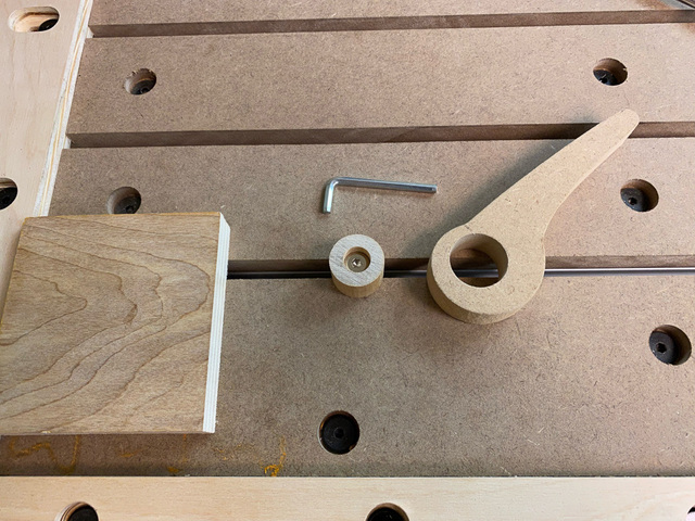
A simple cam clamp would be a minimal solution. The idea was to have a moveable dog that could be fastened along the track, and the cam clamp would pivot on the anchored dog.
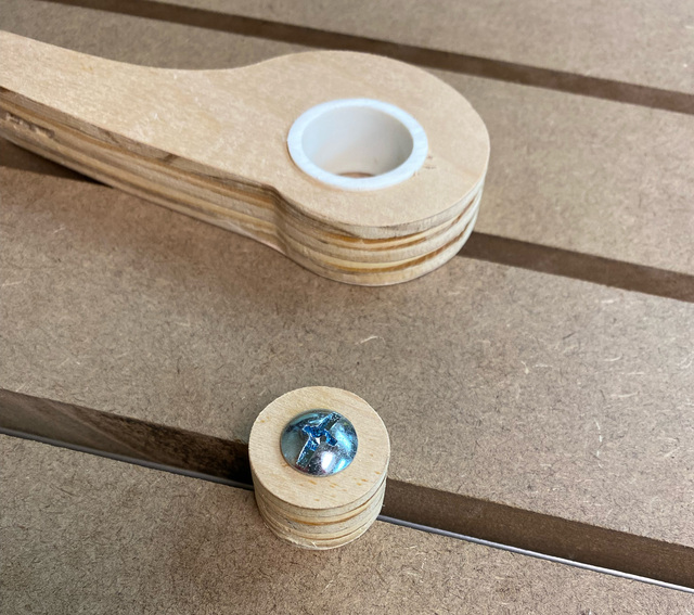
My first attempt was a plywood disk for the dog, a plywood cam lever, and a slice of 1" PVC pipe as a bushing (similar to the hub of my flip-top cart). To fit the PVC pipe within the cam with enough wall thickness on the plywood, I had to scale-up an earlier cam clamp design.
I had sized the plywood dog based on the nominal inside diameter for 1" PVC pipe, which turned out to be a little too loose for the section of pipe I used, so the fit was a bit sloppy and the clamp didn't hold tightly.
Also, with the increased diameter of the spiral, clamping pressure was achieved with a smaller rotation. The limited throw also seemed to make them easier to work loose. It might have been the plywood cam against plywood work, but the cam tended to rotate the work rather than clamping it against the fence.
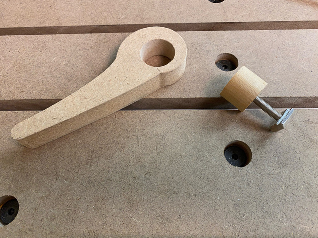
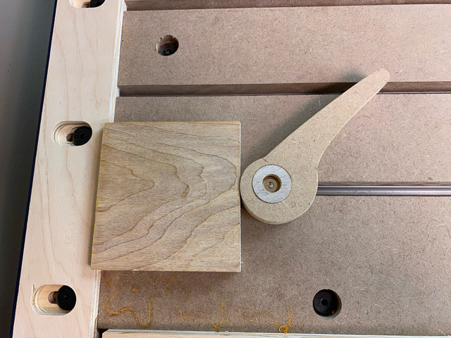
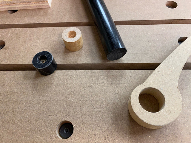
For the next iteration, I reduced the cam lever size, eliminated the PVC, used a section of 1" wood dowel for the dog, and cut the cam lever from MDF.
I counterbored the dowel to drop the bolt head below the surface.
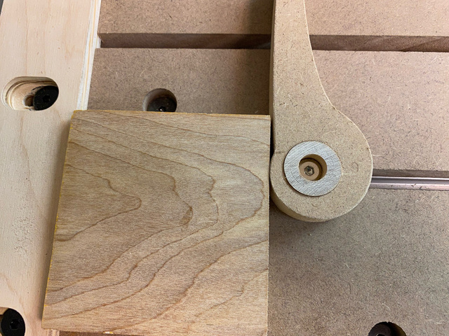
The smaller cam spread the horizontal travel over a greater rotation of the lever. And the MDF didn't grab the work the way the plywood cam did.
I thought that the wood dowel might not hold-up over time - with the pressure of the screw, the end grain could shear at some point. I bought some 1" diameter copolymer rods on Amazon for the dogs, and they'll hold up much better.
I like this simple clamping solution, so I'll make a set of these. There's a couple things that are not ideal:
I need to use a hex wrench to tighten and release the dogs. With the dogs so close to the work, a knob on top would make tightening them a little difficult. It's a minor nit, plus I like being able to temporarily remove the cam lever and then drop it back on when the work is positioned.
Without using a shim, they only work for horizontal clamping along the track. A shim is not horrible, but it requires different sizes depending on the size of the work.
I'm pondering a variation of the Sea-N-Sea clamp that shifts the knob closer to the work. That's up next.
I’ve watched a lot of videos on cam clamps, and I think I’ve only seen one where there was any analysis of the shape of the curve that’s needed for an effective clamp. What I’ve been doing (and I don’t claim it’s the only shape that works) is basing the cam on an equiangular spiral. With this kind of spiral, all radial lines intersect the curve at exactly the same angle. If you choose an angle that’s close to 90 degrees, there’s enough friction between the cam and the clamped surface to hold it in place. These cams are based on an angle of 85 degrees, which seems to work pretty well. The force against the work isn’t perfectly perpendicular to the clamped edge, but it’s close enough that friction will keep the cam pretty secure.
I found this video that discusses the shape and he also has a link to SVG and PDF files in the description so you do not have to design it yourself. It sounds like he took similar spiral approach like Ross did. I've queued the videoto the point where he discusses how he fixed the release problem. I have not tried it yet.
--Nathan, TX. Hire the lazy man. He may not do as much work but that's because he will find a better way.
Thanks Lazy, I came across one of his designs (called the ultimate ....). That link only had a link to a PDF that was near impossinble to import into any software without the need to manually trace over... which defeated the purpose as I was then back to trial and error.
Will try the SVG format... did try the SVG... exactly what I was after... thanks.
If your first cut is too short... Take the second cut from the longer end... LBD
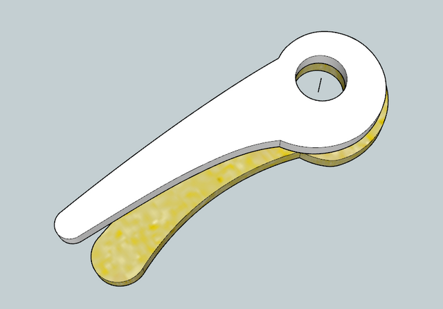
Similar to the one Chucky pointed to, but found it a tad more streamline/fluent, (your's is the white)....
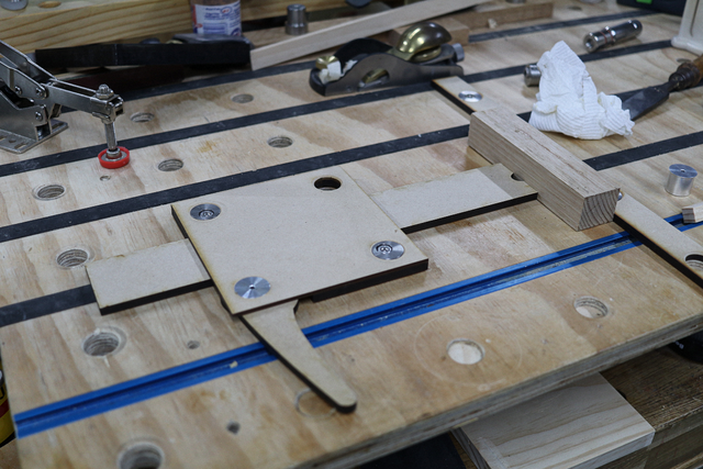
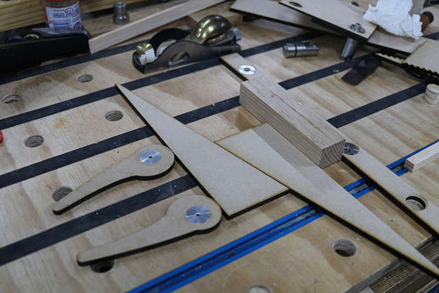
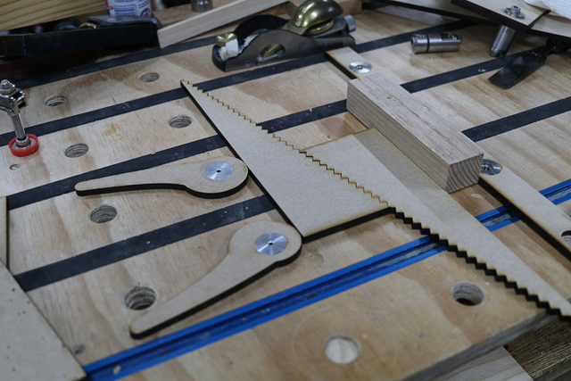
Started to test them out for applying holding force... not happy with take #1, happier with take #2, small toothed (1mm teeth), gruntled with take #3 (2mm teeth), think 1.25mm teeth wold satisfy Goldilocks.
This way I can work unobstructed on as thin as 7mm stock... that big block was just handy at the time... I'd normally use the "standard" gear for thickish stock.
If your first cut is too short... Take the second cut from the longer end... LBD
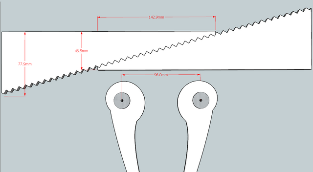
Good on paper and posed photo shoots... When extended to minimise "thickness" you decrease the width of stock clamped... in the diagram that is reduced to 140mm. Minimum would be 96mm (between dogs) because of cam placement, back to the drawing board.
If your first cut is too short... Take the second cut from the longer end... LBD
Lazyman commented about 3 hours ago new I like Marius Hornberger's solution where he used blocks with an off center hole sized based upon the spacing of his dog holes.
It was that concept that made me zip off on a tangent with my zig-zag design.... however, if that board was a tad smaller (thinner) both sides' blocks are at maximum reach, so he would have to add extra padding. Though there might be a squeeze when the cams are closed... basically, the design is more mathematical than just cut and go.
If your first cut is too short... Take the second cut from the longer end... LBD