A visitor to my workshop over the weekend was intrigued by my rectangle centre finder which has prompted me to bring across this article I wrote at Lumberjocks back on Mar 28, 2017.
The jig has since been updated but rather than add the changes here and remove the need to struggle through the original, I will post the changes after the original article… and if you’re tempted to skip to the bottom… there will be a quiz at the end.
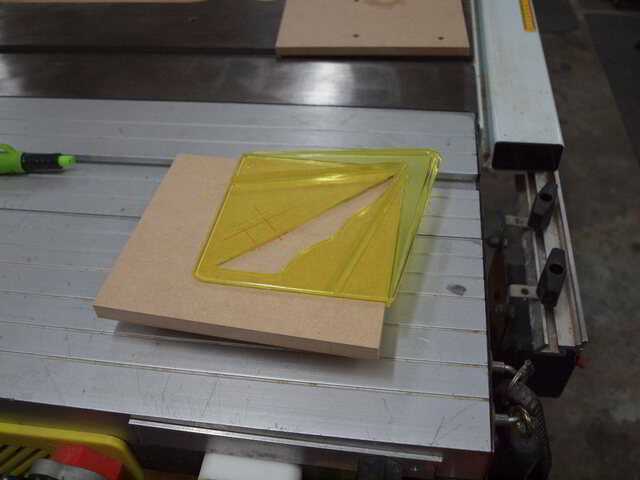
G'day all. While preparing my Small Circle Cutting Jig article, I found that I had to resort to using a particular jig far too many times as I kept stuffing up the video and consequently having to follow that up by marking out more sacrificial pieces of MDF.
The aforementioned jig is my "Rectangle Centre Finder". I'm sure most of us have one of those proprietary centre finder gizmos or made one ourselves,
Let's face it, all us woodworkers know how to cut that perfect square… in the shape of a rectangle.
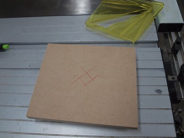
I've found those gadgets great for small squares and circles, however, you don't have to mark and drill too many pieces before you finally realise that the mark was not centred for rectangles… I kept thinking I inserted my drill bit off centre (and for my new drill press that was a no-no).
I challenge anyone to get the ruler on both the opposing corners of a rectangle perfectly alligned in less than 10 attempts (and I may be generous there).
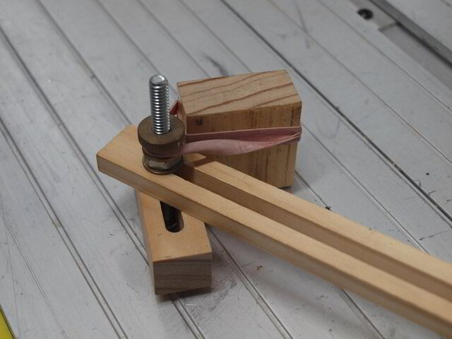
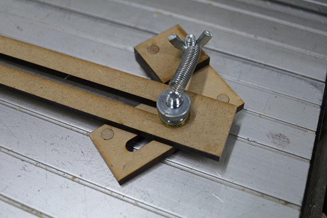
My jig is made out of pine, though hardwood would be more robust. I prototyped it out of pine and as it worked so well I saw (no pun intended) no reason to redo until it eventually breaks or wears out.
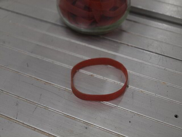
It's held together with a couple of ¼" bolts just snugged up tight enough to stabilise it but not so tight to stop free movement. The secret of the whole operation is the use of 2 Australia Post rubber bands. They seem to provide the best tension and do not break down in the atmosphere like most cheapo rubbers. Just goes to show Australia Post (AP) is good for something else other than paying their CEO $5,000,000 per annum, just to deliver overpriced postage… I deliberately post myself letters, not because I like my scintillating conversation, but just to get more free rubber bands.
For successful operation, it is imperative that the slide is held tight against the corner blocks to ensure a centred line. I found this easier to implement using the AP rubber bands, after abandoning the idea of using springs in many failed and impractical combinations.
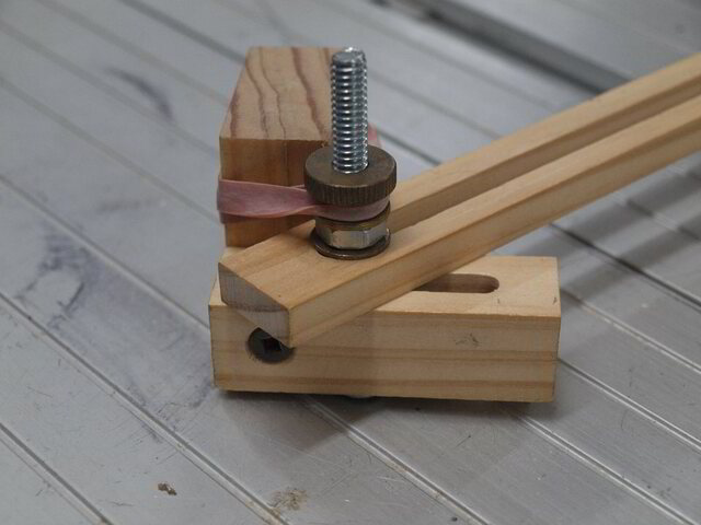
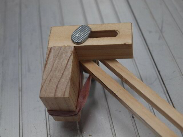
A close up of the corner blocks, hardware and bungee (and the top of the saw table) as I had some film left over in the camera,
Unfortunately rubber bands have a shelf life and the pair could not survive the stretch marks and needed an upgrade.
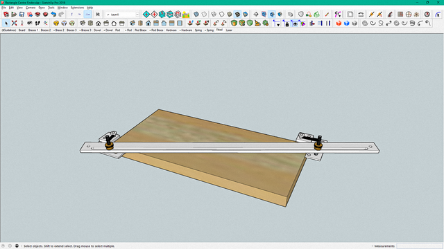
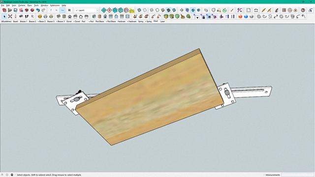
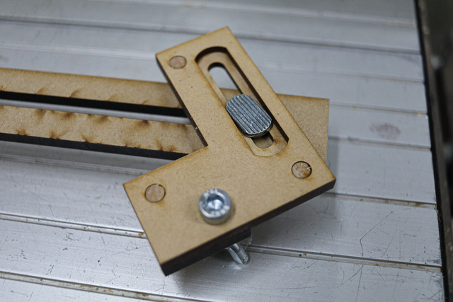
Back in 2017, I could still afford pine, but nowadays MDF is by budget go to and with a few updated jig techniques, a new design took place in SketchUp,
and these are the latest updates.
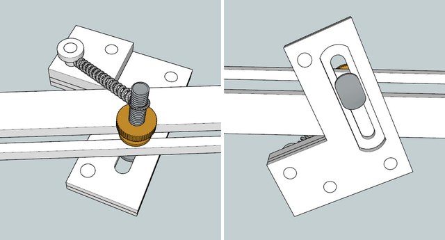
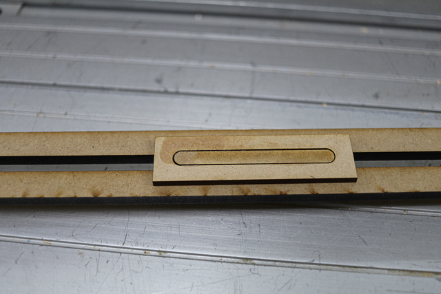
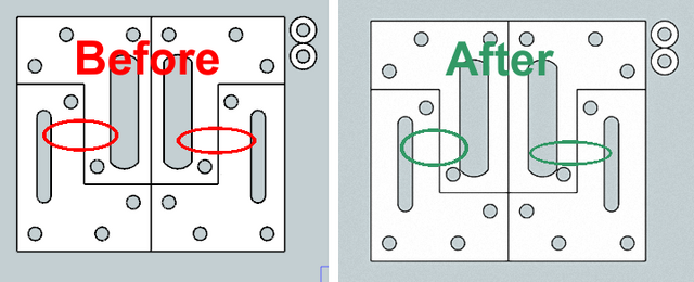
The previous version had a narrower centre rod
with springs
instead of the rubber bands. A fault of the design of the 3mm thick centre rod was that it could be slightly displaced if too much pressure was applied to the pencil while drawing the lines. While this was minimal and could be overcome by pressure down on the rod with the left hand, however, to ensure oopsie prevention, a centre brace was cut out of MDF to provide that missing support,
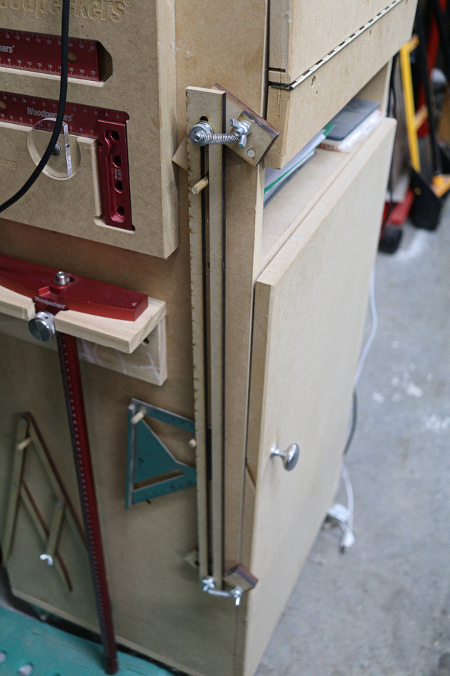
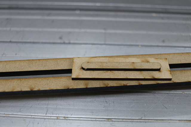
This is still my current jig (not the wider off centre rod) as it still works perfectly well, and with the configuration changes enough that the whole jig would need to be re-cut... probably when I eventually loose that certe brace.
For anyone interested, the upgrade,
Now for that question… how old are you… no cheating and asking the partner.
If your first cut is too short... Take the second cut from the longer end... LBD
sorry ducks dont wanna piss in your wheaties but i can do the same thing with a rular laid corner to corner and drawing a line near center ? am i wrong ?
working with my hands is a joy,it gives me a sense of fulfillment,somthing so many seek and so few find.-SAM MALOOF.
Didn't you read the quiz warning? LBD clearly stated (with that Aussie accent that can be heard while reading) that aligning and keeping the straight edge perfectly corner to corner before tracing was an aggravating experience which I can relate too.
Some nice upgrades with this version Duck! Best part is you didn't make the corner blocks leaving you with both sides of the cross bar on corners (or did you edit out that step???)
SplinterGroup .... you didn't make the corner blocks leaving you with both sides of the cross bar on corners (or did you edit out that step???)
Not sure what you mean by that Splinter. The corner blocks need to align on the same side of the cross bar.
I gave my "old new one" to my friend so after updating the SketchUp for uploading to the 3DW I decided to make a "new new one" and cocked it up. I forgot that the last version had a bug which I only fixed in CorelDraw and didn't retro fit to SU and repeated the mistake again.
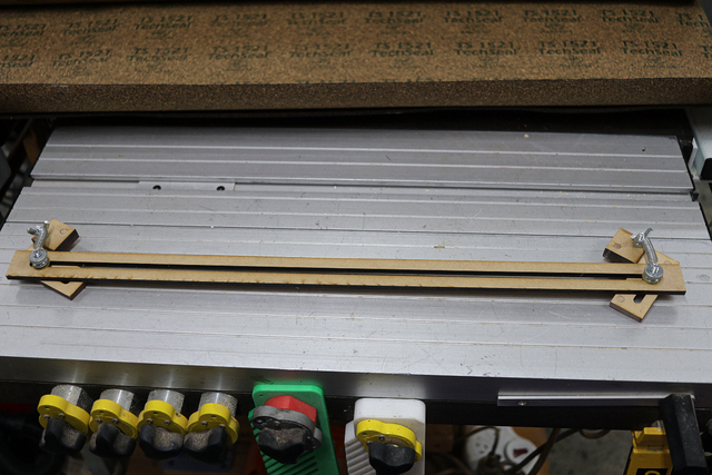
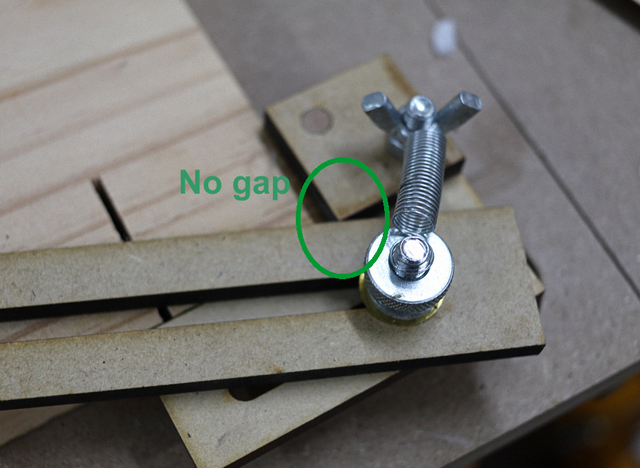
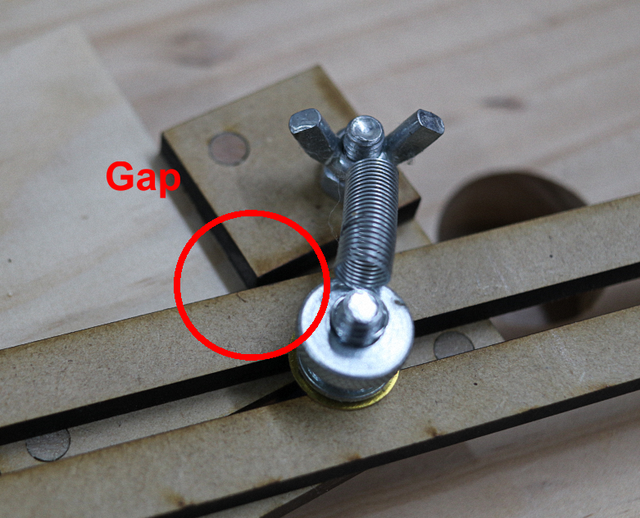
The bar has to snug up to the corners on both ends, however, I found there was a gap on one end, which naturally gave false results.
It turned out that the gap between the rod and the t-bolt anchor was out of whack, and had to be changed back in SketchUp and carried forward, through to the laser. After all this BS, the bottom line is that if anyone was crazy enough to download from the 3DW, there is an updated version sitting there now,
FAIW, it felt good to track down and correct the bug. Being able to manipulate the angles in SketchUp sure beats trial and error in the workshop.
If your first cut is too short... Take the second cut from the longer end... LBD
Not sure what you mean by that Splinter. The corner blocks need to align on the same side of the cross bar.
My point exactly. If I made that from an idea in my head, I'd have messed up somewhere and made it so the corners were on opposite sides. Worse is I wouldn't notice until I noticed the projects looked a bit off center.
At that point I'd dispose of any evidence of the error and make a new one.
Ahh... Capiche! That's why I use SketchUp so often... even for small projects... it's ideal to work out things like arc of swing and what if's rather than ruin a project. I think with the very first stokes of the keyboard I had the blocks mirrored on both sides of the rod.
If your first cut is too short... Take the second cut from the longer end... LBD
It is a very useful jig! Only weak point I see (and you also saw) was the potential flexing of the cross piece. Wondering if there is some common metal item with that slot configuration, similar to the blade of an adjustable angle gauge thingy?
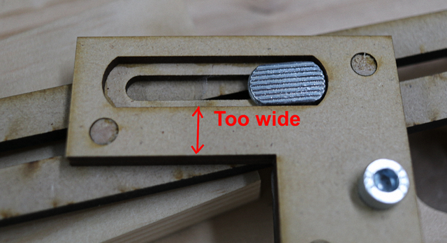
I was initially concerned about the flex and altered the rod accordingly, however, I didn't play with the swing in SketchUp and only found it snafu'ed after assembly. Should have been something like,
That centre brace handles any potential flex as just a tad too much pressure would break the lead before a flex. Also keeping the brace in place is subject to extra downward pressure with the left hand.
If your first cut is too short... Take the second cut from the longer end... LBD


.jpg)


.skp%20-%20SketchUp%20Pro%202018-003689.png)
.skp%20-%20SketchUp%20Pro%202018-003690.png)
.skp%20-%20SketchUp%20Pro%202018-003691.png)