Well, I embarked on a new journey making another type of plane. This time it's making a Japanese Kanna Plane.
A kanna is a traditional Japanese hand plane used to shave, smooth, and finish wood surfaces by pulling the tool toward the user. It consists of a wooden body (Kanna-Dai or Dai) usually white oak and a laminated steel blade (Kanna-Ba), often creating a surface so smooth it requires no sanding.
There are numerous types of Kanna planes. Here are just a few of the main ones:
Common Types of Kanna
Hira Kanna: Standard flat plane for smoothing.
Kiwa Kanna: Specialized for planning inner corners and rabbets.
Sori-Dai Kanna: Used for shaping curved surfaces.
Kanna are essential for fine joinery and furniture making, providing a high-quality finish. There are many different kinds.
Key Features and Components
Pull Stroke: Unlike Western planes that are pushed, the kanna is pulled, allowing for better control and less effort.
Structure: Comprised of a wooden body (dai) and a tapered blade (kanna-ba) that locks into place without wedges. However straight blades (used in western planes) can be used with a chip breaker that tightens with a thumb screw. Kakuri is a known Japanese plane manufacturer that has popularized this type because its easier to set up foe the Western user.
Chip Breaker (Ura-gane vs Osae-gane): A secondary blade that reduces wood tear-out. Ura-gane is the general term for the Japanese chipbreaker, while Osae-gane emphasizes its functional role in holding and pressing the blade, but they refer to the same, crucial component for creating a smooth surface.
Setting Up: These tools often require custom fitting, sharpening, and tuning the wooden sole to the workpiece.
Here's the basic anatomy of a Kanna plane:
The Beginning
I decided to make my Kanna plane using details from a Kakuri chamfer plane that I already had along with researched information.
Japanese terms for the various kinds of Kanna planes confuse me some. However, I think what I making is actually called a βHira Kanna smooth planeβ.
Typically they are made out of Japanese White Oak. Japanese White Oak (Shirokashi) and American White Oak (Quercus alba) differ mainly in density and grain, with Japanese oak offering a tighter, more uniform grain and higher impact strength, ideal for tools and weapons. American White Oak is more readily available, generally stronger overall, and preferred for flooring and furniture, with a more pronounced grain. Japanese White Oak has a Janka hardness of approximately 1,200 to 1,360 lbf (5,320β6,000 N). American White Oak has a Janka hardness rating of approximately 1,360 lbf (1,360 or 1,350 on some scales). They are about the same except for availability. So for my Kanna plane I used American White Oak.
I decided to make this plane by built up lamination style. This approach allows for good accuracy especially if you haven't made one before. It used to be that the only way to make these was by mortising the throat, etc. But now both approaches are widely used and acceptable in the making of Kanna planes.
I began by milling a block of White Oak a little larger 3β ( 76.5 mm ) wide x 11β ( 279.4 mm) long x 1- 1/2β (38.1 mm) high. Then I sliced off two pieces that will be the Sides (Left and Right) at 3/8β (9.53 mm) thick x 11β (279.4 mm) long. The center portion that will be the Front and Rear pieces are cut as blocks and then sloped for the bed and mouth areas. The Bed angle is 38 degrees. The face opposite is 52 degrees.
Here's a dry fit clamped together (Fig 1):
Next, I make a pencil line on both sides of the 38 degree bed (Fig 2). This will allow me to cut the slots required for holding the blade edges. Then I used a blade blank to offset the pencil line accounting for thickness (Fig 3). Then using a chisel, I make knife walls in preparation for hogging out the track with a router plane (Fig 4). This is done for both sides.
Here you see me using my router plane making the tracks (Fig 5)
I knew as I made this that I would be taking it apart back and forth checking details and refining the process. I wanted all the pieces to always go back together accurately as I worked. First, I made the overall block length a little longer than 11β. Doing this allowed me to temporarily dowel pin (Fig 6, see red arrow) all pieces at both ends and after all is said and done I will glue these in at final assembly and cut to the finished overall length of 10β.
Here you'll see why the temporary dowel pinning helps in the build process, Fig 7.
I can take it all apart and back together again with perfection registration Fig 8.
Here's a test fit of the blade blank in place per Fig 9 and the blade and chip breaker together per Fig 10 .
Making the Blade (Kanna-Ba) and the Chip Breaker (Osae-ba )
I start by cutting two blanks out of 1095 steel. One will be the blade at 2β wide x 4-1/4β long x 1/8β thick. The other is the chip breaker at 1-1/2β wide x 3-1/2β long x 1/8β thick. I start by perfecting the blank shape for each by passing through the grinder shown here per Fig 11. Afterwards preliminary 25Β° bevels are put on both.
Next I put a 1-1/2β radius on the the top of the blade (Fig 12) and 1/2β radius on each corner of the chip breaker and then both housed for a fit (Fig 13).
On the chip breaker I tapped a 1/4-20 threaded hole for adding a brass knob. Here they both are per Fig 14. We now proceed to Hardening and Tempering the blade.
Annealing, Hardening, and Tempering
Annealing
Next I heat treat the blade. I anneal it. This removes the hardness from the steel. Doing so makes it easier to shape the blade and fine grind the bevel. I usually do this in a vise with my hand held propane torch and heat about a half inch down from cutting edge and across the width until it reaches a bright cherry red color or bright orange. The important thing is reaching the Curie Point. This is approx 1400Β° F and the steel at this point loses its magnetism. You touch it to a magnet to be sure then let it air cool or stick it into a bucket of sand to cool it slowly. However I have found it difficult to do this with blades much wider than 1-1/2β to 1-3/4β. The blade is very difficult to get to the Curie point because the bulk of the steel transfers the heat away while you are trying to get to that Cherry red / Bright Orange point. So I use a small forge to provide a much hotter environment for the blade and able to reach the Curie point with my propane torch much easier.
Re-Hardening
After I complete what grinding and shaping I need to do it's time to re-harden the blade. Again you bring to Cherry red / Bright Orange point, check with magnet to make sure you are at Curie point, then plunge into oil to quench it. This hardens it. You can check to see if a file will glance off of it. If it does it harden. I use old auto oil but many do not like this because it could flash and it stinks. Peanut or Canola oil works well too and have higher flash points.
Tempering
There are a couple of ways to do tempering. You can place in your oven or toaster oven at 375 β 400Β° F for 1-1/2 to 2 hrs and let it completely cool down or you can do it by hand in a vise. The oven method usually is done twice. The process is more controlled but it uses a lot of energy just to do a blade and you do have to baby sit the process to make sure it doesn't go past a straw color. Then you have the waiting time to let it cool which can be longer than an hour. It can take over 6 -7 hrs when all is said and done. My wife wouldn't be too happy. Of course you can use a toaster oven if you can find one with stabile consistent temperature. The hand held method is done in the vise as mentioned under annealing above. You torch the blade about a half inch down from cutting edge and across the width until it reaches a straw color.
BUT....once the color starts it moves towards the edge so fast that its easy to ruin. If you go past the straw color then its likely ruined and you have to start all over again. I use a another piece of steel sandwiched under the blade's bottom and heat with the torch from the underside of this piece. This slows the heating process for the blade on top and gives you time to react when you see the straw color. Normally tempering is done by allowing it to cool naturally once you see the straw color at the cutting edge. But I have found that a quick quench in oil stops it from going past the straw color and being ruined. This is particularly true with 1095 steel. Ron Hock, who is known for making Hock blades (now owned by Lee Valley), quenches in oil when tempering.
Here's my blade tempered (Fig 15) and ready for final honing.
Now I glue all the planes parts and clamp them together. When its dry, I'll remove the clamps and cut off the front and rear portions of the body. (see the red dotted lines). This will resize the plane's length to the final 10β long. See Fig 16.
The completed body (Dai) is 2.5" (63.5 mm) wide x 10" (254 mm) long and 1-1/4β (31.75 mm) high and as mentioned previously is made out of American White Oak.
Relieving the Bottom
The process of relieving the bottom is necessary because it reduces the friction and provides effective planing. This was was a challenge for me. Hard to relief it 0.015" ( 0.038 mm) as required on all kanna planes. See Fig 17.
On the bottom of this plane I chose three points of contact as shown in Fig 17 above. These three areas are all on the same plane. I used a card scraper to do these relief areas. I set it on top of my cast iron tablesaw and checked the bottom for the .015β gap by using a feeler gauge. You could also set it on plate glass and measure your progress as well. I only had to do this a couple of times.
Per Fig 18, I start by penciling out boundary lines and cross hatching indicating the areas to be recessed. Red arrows indicate areas not recessed and lay in the same plane (the original bottom). These areas are 1/4β by the plane's width.
Then per Fig 19, I green tape it to provide better visibility and cover the areas that wont be recessed. All hatched areas (look closely) are ready to scrape down 0.015β. Gads!!
Here in Fig 20 is the process in action!! Keeping it dead flat was a challenge.
Here in Fig 21 and Fig 22, I am checking all the recessed areas as I go to achieve the .015β. I hold up to light and use a steel rule straight edge to monitor the gap and then check with a feeler gauge.
Here per Fig 23, it is finally completed and everything is dead level and perfect!!
awesome plane making my friend. i love the japanese tech on how they pull, as in "pull saws " rather than western style push ! it makes total sense. probably why i have many pull saws !
working with my hands is a joy,it gives me a sense of fulfillment,somthing so many seek and so few find.-SAM MALOOF.
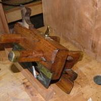