Share your craft projects
Make new craft buddies
Ask craft questions
Blog your craft journey
50 Replies
I think you would be taking the right approach making a prototype,perhaps a very dense wood like Ipe might work or dadoing out the inside and using a metal reinforcement frame. on the inside.It certainly would be a challenging project.
woodworking classes, custom furniture maker
Rennners: Great Question, and thanks for offering it out for feedback.
(with a broad smile – ) Brave AND Stupid are not necessarily mutually exclusive; though everything becomes a sum of its parts…. My guess is that what makes it Brave is the somewhat Stupid part…
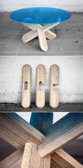
From the picture, it’s difficult to see the base, in 3D; that is, I can’t tell how the legs are joined, if there are right and left legs joined (cross-member, perhaps) or they intersect in the middle (like a large X)
Also, from the picture, the wood appears to be 8/4 (50mm) Walnut (pricey…), though, I’m not an expert in this. Also, there appears to be a double taper to each leg (narrowing in the center, tapering out to a wide ends. The glass is probably tempered – again, pricey – and relieved on the edges.
If the legs form a large X, then the very difficult question of the central mortises and tenons, if that’s how you would do it. My initial thought is to half-lap a small central section, then secure (Top-to-Bottom, through) with a 1" (+/-) walnut peg. My guess is that any type of nut & bolt arrangement, though expedient, would loosen – if you use a nut & bolt, rather than the peg, this would allow dis-assembly; and you may be able to achieve sufficient tightness with a washer, lock washer, and double-nut arrangement – though, you would have to conceal this joinery, for appearance sake. In either case, the central joint would need to be fairly robust to allow for a large Nut & Bolt or walnut peg. There is a possibility that a large half-lap, alone, would be sufficient; however, I’m skeptical that this would be strong enough; and rigid enough. .
Regarding process -
The overall quote should cover (be large enough) to support the prototype cost – unless you want to take this on as a learning experience.
The prototype – I would start-out with Pine, Douglas Fir, or an inexpensive hardwood – to test approaches to the central joinery – you can approximate the weight with plywood and cement blocks laid onto whatever prototype leg assembly you build.
These are my initial thoughts – I hope they’re helpful.
MJCD

To be able to build something like the table you pictured would be a dream, though I have no clue how to go about it. From a cost perspective, everything I’ve ever researched and read about the subject of custom furniture and design leads me to believe the cost of the prototypes should be passed to the customer. Anyone serious about requesting a one off custom design such as this should be prepared for the price tag that comes with it. I hope you are able to land this, and at a worthwhile price. I’d love to see the finished product and hear about the build process! Good luck!

I don’t care much for this particular design . Visually , it looks unstable . It looks structurally sound as a rock , and probably is .
That may be the designers’ way of showing the cleverness of his joinery ,drawing
one’s eye to the ‘Gordian Knot ’ of the tapers towards the joint .
You could shop this around to some timber framers ( don’t know
what they are called in Ireland : ) ).. , and see how
much they would charge you to build it , as a reference for your quote .
Lazy factor aside, I’d have no qualms about taking on a project like this. With the right joints, the down pressure on them would only increase the safety factor [of the assembly supporting the glass.
I would take some doodling, but many are the approaches, I see, possible. All would be in the mortise and tenon category, but they could vary from wedges like dove tails to just straight cuts. Of course, all would only go into each leg only as much as needed to assure a joint and to allow all for legs to get in on the game.
In the end, it boils down to nothing more than some nasty angle work, but some short, vertical 2×4′s (cut just long enough to support the glass) to temporarily hold things in position would give you the feel of a starting place.
I’m guessing you’re going 7/16" if not 1/2" of tempered glass.

I am thinking that the only way to make that strong enough is to use 8 pieces of wood cut the same and then joined to a hidden metal contraption in the middle with 8 flanges on it. All glued with the best epoxy money can buy. The angles will be a bitch, but when figured out all should be the same.
Good luck Renners.
Tor and Odin are the greatest of gods.

I used to work in the furniture biz. That thing has a steel frame, cleverly hidden. That’s a lot of glass to have suddenly hitting the floor.
-- Alec (Friends call me Wolf, no idea why)
I agree it, likely, has a steel structure inside.
Do you think the girl’s feet are strategically positioned to hide the joint ?
I’ll make it unanimous – some metal fixture is necessary. I didn’t want to be the one to say this couldn’t be done with some clever, really outrageous wood joint that the truly gifted members of the forum could recommend.
MJCD

I think the legs are made of steel, welded together, then either faux painted or veneered.
Figuring out how to do something you have never done is what makes a good challenge.

Renners…..welcome to the wacky world of commission furniture making. Sometimes you get some really strange requests, but sometimes you get some really cool ones. This one looks pretty cool, albeit very challenging.
As far as the prototype is concerned, not only is it a good idea it is often a requirement and most definitely should be a part of the bid. The prototype allows you to work out tricky details, develop the construction methods, and serves as the approval process with the client. Depending on the project we may have several points of approval on a prototype that are part of the overall contract. The time and materials dedicated to that process are certainly billable items.
Find out where this picture came from and either visit the site or request more pictures. Too little information is contained in this one picture. I wouldn’t try to speculate any further about construction without clearer details.
We do a lot of commission work off of pictures and simple line drawings. The key is to figure out how they invented that “wheel” and recreate it without re-inventing the wheel.
Artisan Woodworks of Texas- www.awwtx.com
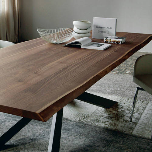
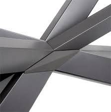
google – cattelan italia spyder italian dining table
Lots of styles/views to look at. Some sites have pricing, some say they are metal, but offer walnut, couldn’t find if it’s solid walnut or metal covered in walnut.
Starting with solid chunks and band sawing them to shape may be an option if you can figure how to join them.
Figuring out how to do something you have never done is what makes a good challenge.

I think the legs cross to a center point. Laminated legs should strong enough and yes wood.
I was looking at those pictures:
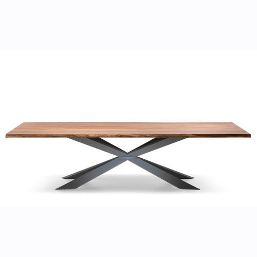
I think this one is really cool ( from the same designer)
Definitely doable and stable
Abbas, Castro Valley, CA
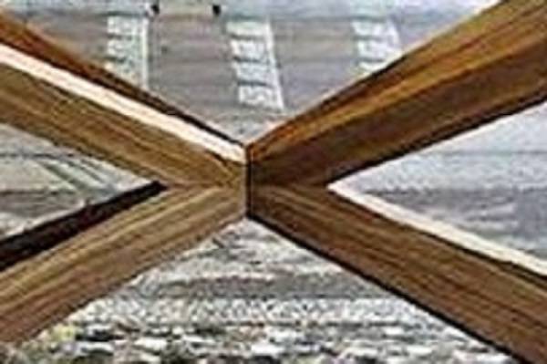
Best picture I could find showing the joints.
Looks like 8 seperate legs, all butt joined in the center.
Mortised, doweled, glued and screwed???
Figuring out how to do something you have never done is what makes a good challenge.
ahhhhhh……pictures….hummmmm…….thanks for the link Bentlyj
Spyder Wood Dining Table from Cattelan Italia at YLiving … plane of timber, subtly raised above two rectilinear leg constructions and detailed with box joints.
The diamond shaped piece at the intersection of the legs may be more than ornamental. Without serious reinforcement I don’t see that joint holding that much glass and whatever might be placed on the table. The diamond pieces look to me like camouflage.
Don “Dances With Wood” Butler

Thanks everyone for your input. I’ve spent a bit of time looking at the manufacturer’s site and retail sites for this piece. I am of the opinion it is a metal construction clad in timber as they offer a walnut or wenge ‘finish’. I’ve put a price in to the guy with a ‘region’ big enough to get a metal substructure fabricated if needs be, stating that due to the unusual design, I can’t work out an exact figure as I don’t know exactly how long it will take to do, and pointing out that the unusual joinery will need a prototype making first to check for weight bearing.
That’s about all I can do. If he balks at the estimate, well that’s down to him. If he wants it done dirt cheap and is willing to take a chance on it collapsing on his dinner guests, he can get someone else to do it. Or he could buy one in a shop in England and get it transported over for about €7,000.
Doing the best I can with what I've got

That is one beautiful table. If you get the job please please PLEASE post progress photos.
Losing fingers since 1969
Rennners:
Thanks again for getting us involved: posts like this make us become a community…
MJCD
I agree with Brian, please keep us in the loop. That table is beautiful. I’d love to see how you do it.
-- Alec (Friends call me Wolf, no idea why)
I know a way to do it out of wood that I think would be strong enough!
If you get the job and are interested in my idea I will be glad to share…
Figuring out how to do something you have never done is what makes a good challenge.
Here’s an update for you, the estimate is out of this guy’s price range, so ‘being an engineer by trade’, he is considering having a metal junction fabricated for eight legs to be inserted.
Wants to know what size timbers to use and would like me to prepare the legs (eight pieces of wood) and organise the glass to make the table.
This equates to a lot of running around, a lot of liability (I’m thinking of the €1300 piece of glass), for little or no reward.
I politely declined to be his lackey.
Thank you all for taking the time to contribute to this thread. I feel terrible that I have wasted your time.
Doing the best I can with what I've got
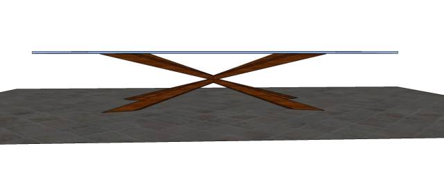
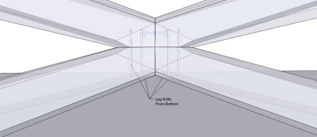
I don’t feel any of my time has been wasted. For me it’s all educational and I enjoy checking out these type of situations. In fact so much so that I tried to draw the joint and show my attachment method for the heck of it.
(Hope you don’t mind)
The following is just for conversation if anybody is interested.
My drawing is not correct but I think it gets the point across of how I would entertain doing it.
I don’t know how well it would work, but that is what’s fun about discussing it.
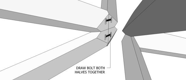
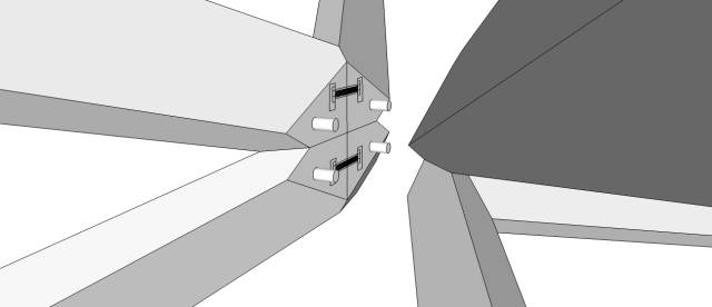
In a nutshell, (up for opinions)
I would make 8 separate legs from solid material with the proper angles cut on the ends.
I would bolt the top and bottom legs together for each diagonal section first.
Then I would draw bolt the two halves together to make a side,
Then I would dowel the two sides together. Glueing the crap out of everything.
Here’s my pics. I don’t know if this would be strong enough or not, but it is what I was thinking if I had to do it. What do you think?
Figuring out how to do something you have never done is what makes a good challenge.
Rennners: That is not wasting our time. I had fun just trying to find a way to make the damn thing. Lubricating the old brain cells you know.
Tor and Odin are the greatest of gods.
Rennners:
NOT a waste of time – Thanks for taking us along with you.
I’m trying my best to learn Rocking Chair making – in real time… it’s daunting!
MJCD
Nah, thanks for the mental exercise, Renners…too bad he wasted yours, though.
Fabulous drawings, BentlyJ but I’m still not sure there would be strength enough, still…smaller table maybe…Anyone to try a coffee table?
-- Alec (Friends call me Wolf, no idea why)
Thanks for your understanding guys, such a disappointment though, I really would have loved to have had a crack at that job.
Bentlyj, you are the Sketchup Sifu. In your drawing I think the bottom four members would be fine in compression, in fact, the design would push them together, but still not sure about the top members wanting to splay. Then again, to be honest, I’m not an engineer or a materials analyst, is the 100kg weight equally distributed on all the joints? Would the top legs each have to carry 25kg (a bag of cement), or does the distribution mean they only have to carry 12.5kg.
My initial thoughts on this project was to make one X and then using all thread, attach the crossing members through the X. I thought of making it as a hollow form in oak and veneering it with walnut to close it all up.
Doing the best I can with what I've got
In my experience I have found these kind of inquiries yield about a 10% return. Most folks don’t understand the amount of time it takes to do a one-off project and are unprepared for the price. But keep bidding them because eventually one will hit. You’ll also learn to think in more abstract terms which will help the design and bid process.
Personally, I’d approach that table with more of a saddle joint configuration. I don’t think the design bently did would take the weight, but it’s a good start. The joints need to compress on themselves handle the weight.
Artisan Woodworks of Texas- www.awwtx.com
Really loved this discussion. More of this would not be annoying :) Much more fun than should I buy saw A or saw B. That was a real puzzle. that was a really hard quote and that was a beautiful table. What’s not to like?
-- Alec (Friends call me Wolf, no idea why)
How about a piece of wire connecting the 4 upper legs to each other and the same for the bottom? Then the weight would compress onto the joint. I don’t think it would take much of a wire and would be practically invisible. Just make sure it’s secured well. ;-)
Losing fingers since 1969
Stay tuned! 1/2 a test coming soon, to a theater near you…:)
Figuring out how to do something you have never done is what makes a good challenge.
You are the Man Bently!
Abbas, Castro Valley, CA
lol, just havin fun killen time….
Figuring out how to do something you have never done is what makes a good challenge.
You could park an elephant on that
Doing the best I can with what I've got
Still not convinced….but I want to see it work.
-- Alec (Friends call me Wolf, no idea why)
I would go for a longer draw bolt so I have more beef on the cheek.
But as it is it should work since there is the bottom portion. so when glued it should be even stronger.
Abbas, Castro Valley, CA
RESULTS: FAIL
The joint didn’t hold, so the ney camp wins.
I was really surprised though, I thought it would hold.
There are some differences though compared to what the finished table would have been. First I’ll list the things that went against the test.
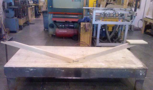
The table legs were 8’ long total, (48" each half) This may have been longer that the original base would have been therefore having more leverage, putting more pressure on the joint.
It was only half the leg, I think it would have been stronger if the other half were glued and connected to it.
It was bolted through 3/4 plywood and when the joint failed it actually pulled up and fractured the plywood. Not sure if the solid bottom legs would have helped or not.
The endgrain didn’t hold much glue, I should have drenched it but don’t know if it would have helped any more or not. I did smear both sides, waited a couple of minutes then added another layer and put it together.
Again I was surprised of the pressure exerted on the joint.
I think the last negative was that I put a 100 lb bag of sand out on the edge. I think that figures to a 400lb top. I probably should have started with 50lbs and went from there.
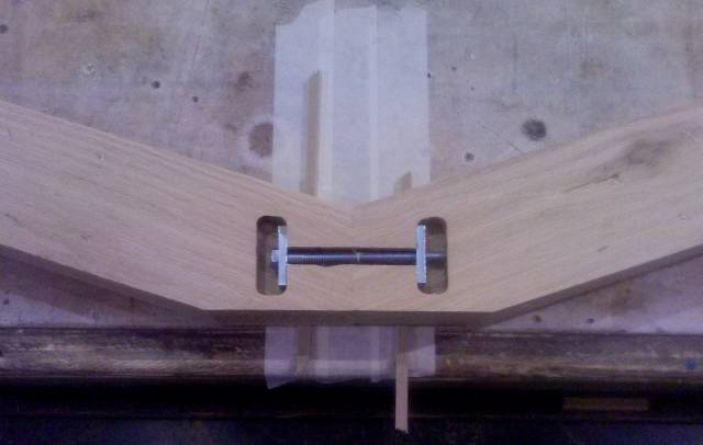
Here are some pics, not very scientific, but you can take whatever you can from it.
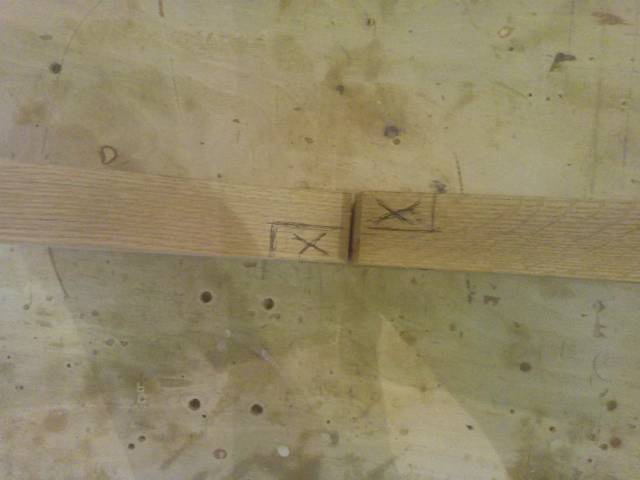
Here are the lags I used, pre-drilled into the legs.
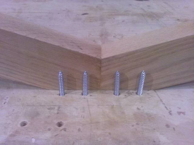
Here is the overall span of the base legs, I added a bar clamp at the opposite end to counter the pressure
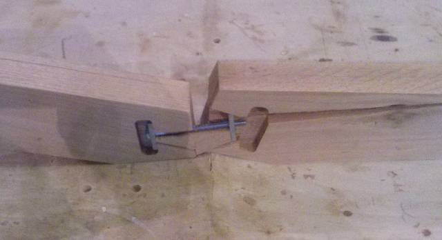
Here is the failed joint. The oak just cracked and split, and you can see the glue didn’t have much bite on the endgrain at all.
In conclusion, I think the table could still be doable. I think Bill’s saddle joint idea or even cutting some half laps would be the way to go.
And now I bow out with my head hung low, but I had fun anyhow. On to the next!
Figuring out how to do something you have never done is what makes a good challenge.
Well done! I’m surprised at the carnage and was rather hoping it would work…Still that’s a long lever.
-- Alec (Friends call me Wolf, no idea why)
This has been worth following! Really cool to see Bently apply his idea in a real world test. I was trying to figure out if it could be done in four pieces, basically two intersecting x’s. I played in sketchup at lunch, and going by the dimensions in the links above, tried to recreate the table. Just joining each leg to make up the x was a chore in and of itself due to the angles involved, and when it came time to try and join the two x’s together, forget it. I still have a headache…It’s still been fun to think about though!
An exercise like that is never a waste of time, it’s a learning tool. FWIW, the reason I doubted that design is because I tried a similar joint in the past. What I discovered was the long fibers of the stock were needed to carry the load, and that is why saddle joints can be so effective. The design you came up with is a good design for non-load bearing application. Keep in mind end grain has virtually no strength whatsoever regardless of how much glue you use (trust me, I’ve tried way too many times to disprove that!). Notice how the wood split along the grain…that’s the strength you have to work with.
Thanks for the effort!
Artisan Woodworks of Texas- www.awwtx.com
I knew I wasn’t going to get much from the end grain, that’s the reason I elected to use the draw bolt.
What I didn’t expect was the board splitting with the grain like it did.
It was a new learning experience for me.
Figuring out how to do something you have never done is what makes a good challenge.
That was a great experiment Bently!
I for one still believe it would have worked with few modifications.
Regardless of the results, it’s a great process you went through and I am sure many of us admire your effort. Another lesson learned for me.
Thanks!
Abbas, Castro Valley, CA
I am surprised that joint failed Bently, Thanks for taking the time to do that and posting the results.
Looking at it, I’m curious as to how the load would be distributed on that frame, is the bottom corner of the leg acting as the fulcrum, thereby adding leverage to the load? Is that why it failed?
Does anyone have any answer as to how the load would be carried on a frame like this?
If the top is 100kg, do each of those members carry 25kg?
Just curious. I’m feeling better about passing on this one now.
Doing the best I can with what I've got
I am by no means an engineer, but just looking at the angles involved that the load at that joint that failed is in the 100-200 kg range, maybe even a lot more. If the legs were vertical then each of 4 legs would carry 25 kg given a table top of 100 kg. We must have an engineer in this group. Please tell us the loading on this joint.
Tor and Odin are the greatest of gods.
Ok, so I did a little research, and this is why the joint failed…
Doing the best I can with what I've got
Of course! I should have known that, I did do the course in philosophy at uni, after all.
-- Alec (Friends call me Wolf, no idea why)
Great resource Kelly
Abbas, Castro Valley, CA
A variation idea: http://www.pinterest.com/pin/552957660471086623/