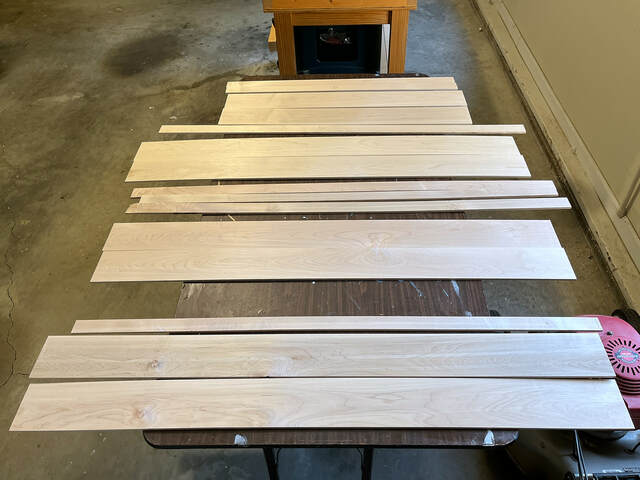
The back panel is sort of a hollow shell around the sliding mechanism. I wanted to keep it low-profile and as light as possible. (I’m using drawer slides in an unintended way, so I don’t want to stress them at all.) I decided to build it with 3/8” slats with a thin (1/4” thick) frame. At the start of the project, I resawed 4/4 maple boards to the required thicknesses. Some of the resawn boards were quite bowed.
The 1/4" boards bowed the most, but that didn’t concern me much. Most of that stock was for boxes and shelves, and the lengths were short and the parts joined which would help with alignment.
The 3/8“ ones weren’t badly bowed, but they weren’t flat. That was a concern, because I wanted the slatted back panel to be as flat as possible to avoid alignment problems with the boxes and shelves it would hold. I thinned the stock another 3/32” so it would flatten when pressed with light finger pressure. (This will be important later…) I planned to glue a 1/4" plywood backer to the slats, and I thought that would help flatten them sufficiently.
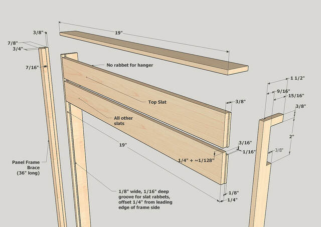
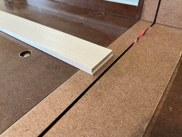
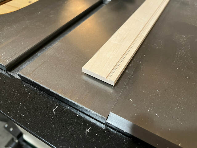
I decided to use tongue-and-groove joints to attach the slats to the frame sides. The tongues are tiny—1/16” deep and 1/8” wide, and the corresponding grooves in the slat ends are equally tiny. I cut the tongues on my table saw with my crosscut sled and a flat-top-grind blade.
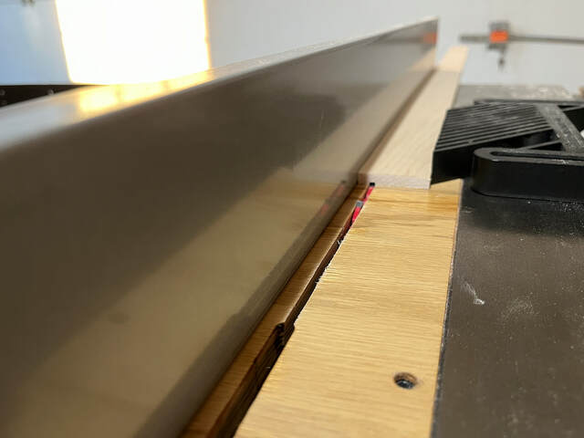
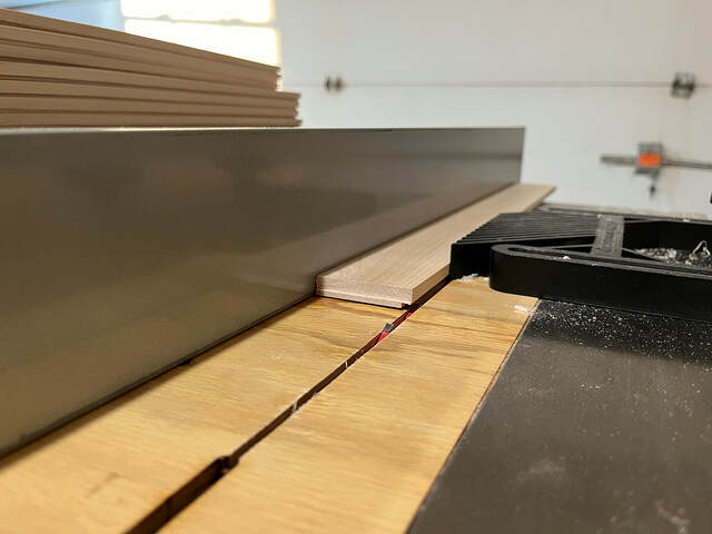
I used very shallow rip cuts with the same blade to cut the grooves in the frame sides.
To finish the slats, I used the same setup to cut the notches for the hangers. I just had to move the fence.
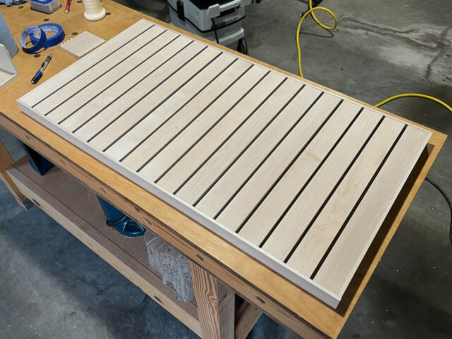
Now came the harder part—figuring out how to glue up the panel, which consisted of 17 evenly-spaced slats and the frame.
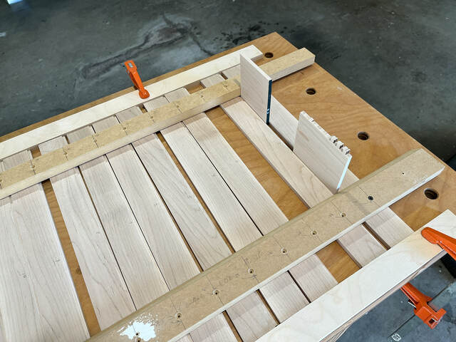
My first idea was to cut two temporary braces and screw it to all the slats with the proper spacing. Then I could glue on both sides at once. I predrilled all the holes in the braces, then screwed them to the top slat. Then I worked my way down, using 1/4” thick scraps as spacers.
That approach seemed fine, but it simply didn’t work. There was just enough variation in the relative heights of the slat ends that I couldn’t fit the sides. If I had used thicker sides with deeper grooves (or if I had moved the braces closer to the slat ends), I think it would have worked. Anyway, I moved on to Plan B.
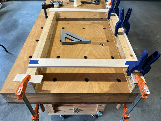
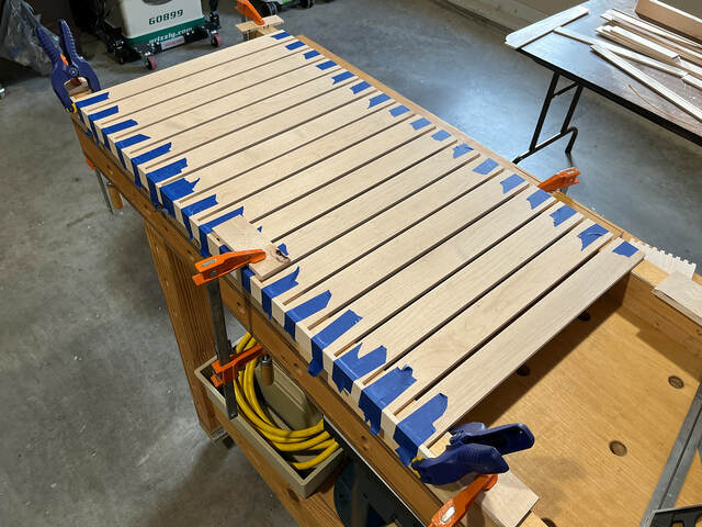
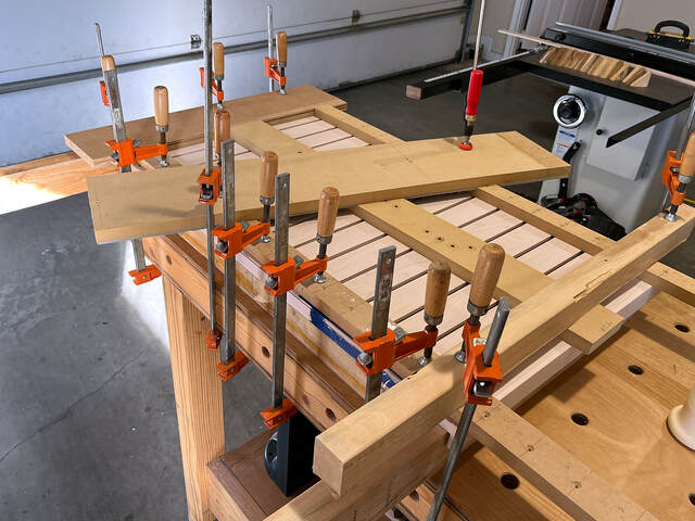
I clamped the left frame side to a tape-covered caul I use for wide-panel glue-ups, and I clamped the caul to my bench so it wouldn’t move. I then clamped another caul where the right frame side would go. I glued the end of the top slat to the left side, made sure it was perpendicular, and taped it securely. Then I taped the other end of the slat to the other caul.
I worked my way down to the bottom slat, again using scraps as spacers.
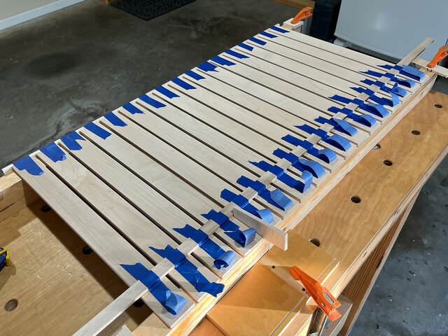
After the glue dried, I moved on to the right frame side. I started by taping a long cutoff to all the slats to stabilize them. Then I peeled back the tape holding the free slat ends to the caul.
I applied glue to all the ends, attached the side, and folded the tape back down to clamp the side. Before the glue set, I checked all the inter-slat gaps and made any necessary adjustments.
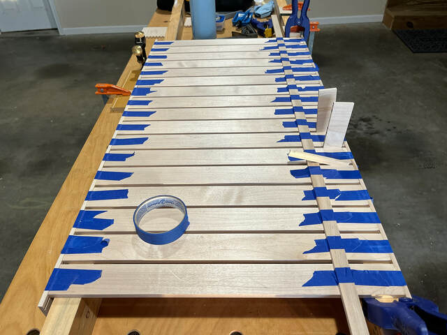
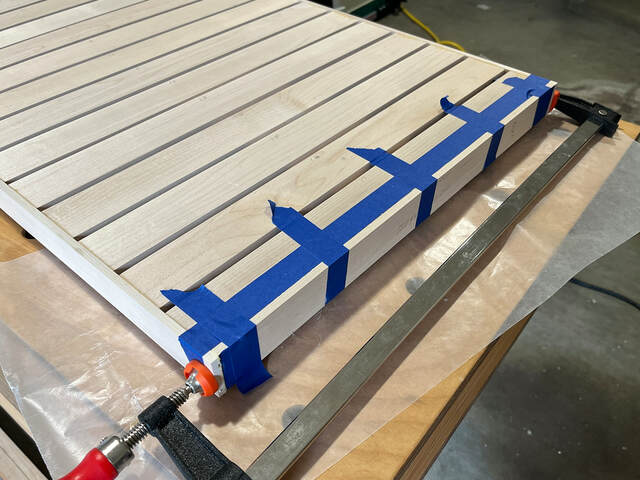
I left the frame sides over-long. I wasn’t sure how closely the spacing would match the model (the gaps between the slats wouldn’t all be exactly 1/4”), so I didn’t know what the exact end-to-end distance would be. I trimmed the excess later, after I had attached the frame’s top and bottom. That was simple: more tape clamps, and bar clamps to close the outer (butt) joints.
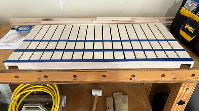
It was nice seeing the mostly finished panel. It was at that point that I realized I had just built a miniature shipping pallet.
After trimming and sanding the ends of the frame sides, I filled the open ends of the grooves with glue and sawdust.
Now I was ready to glue on the plywood slat backer. It was intended to stabilize the panel and block the view of the breaker box and surrounding wall through the slat gaps.
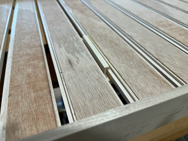
Before doing that, I test-fit some random hangers. Unfortunately, the backs of the hangers protruded past the back faces of the slats. Then I remembered that I had planed the slats down more than first intended to make them more flexible and easier to press flat. (Due to illness and family visits, several weeks had elapsed since the original planing, so I had forgotten.)
To fix that, I glued a strip of two-ply veneer to the back of every slat. They’re about 3/32” thick, which was just enough to bring the slat widths back to 3 /8”. In this photo, you can sort of tell that the back of the hanger is above the back of the original slat. It’s hard to tell, but the back of the hanger is flush with the back of the veneer.
With that problem solved, I glued the backer panel to the slats. I did that with the panel face up so no glue squeeze-out would drip onto the edges and visible faces of the slats. Clamping the backer along the sides was easy, but clamping it in the center was more difficult. I ended up placing another caul under the center of the backer and using more cauls on top to apply pressure. The glue-up didn’t need to be perfect. It just needed to be good enough to securely attach the backer to the slats.
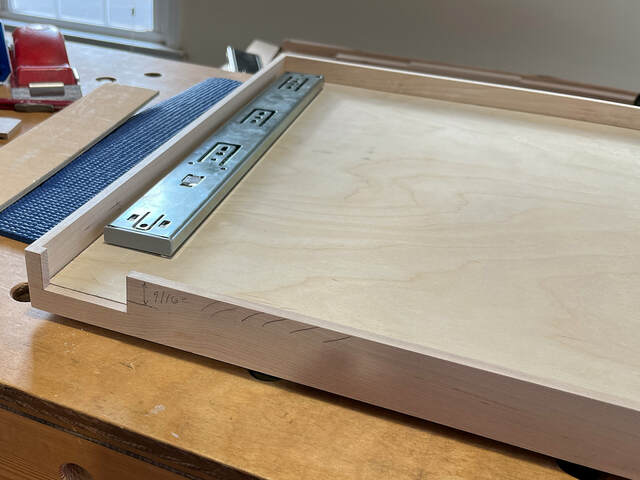
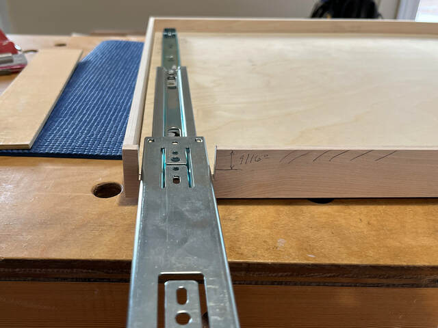
Now all that remained was cutting away some of the frame’s right side to provide clearance for the drawer slides and mounting bracket as the panel opened. This step would have been much easier pre-glue-up, but I didn’t do it then because I didn’t know exactly how long the sides would be.
I cut the two slide clearance notches on the table saw with my crosscut sled, which is large enough to hold the entire pane. I raised the blade to the height of the notch and made several passes until the notches were the proper width. That was the easy part.
The last step was trimming away the bottom edge of the side between the notches to provide clearance for the mounting bracket. That turned out to be much more difficult than anticipated.
I thought about using a straight bit on my router table, but that would mean balancing the panel assembly on its edge, and that would be tricky.
I thought about mounting a slot cutter bit in the table and running the panel assembly face down over the table to cut off that section, but I couldn’t raise the bit high enough.
I thought about using the same slot cutter bit in a handheld router with an edge guide to control the depth of the cut, but the bit was too large for the bit cutout in the edge guide.
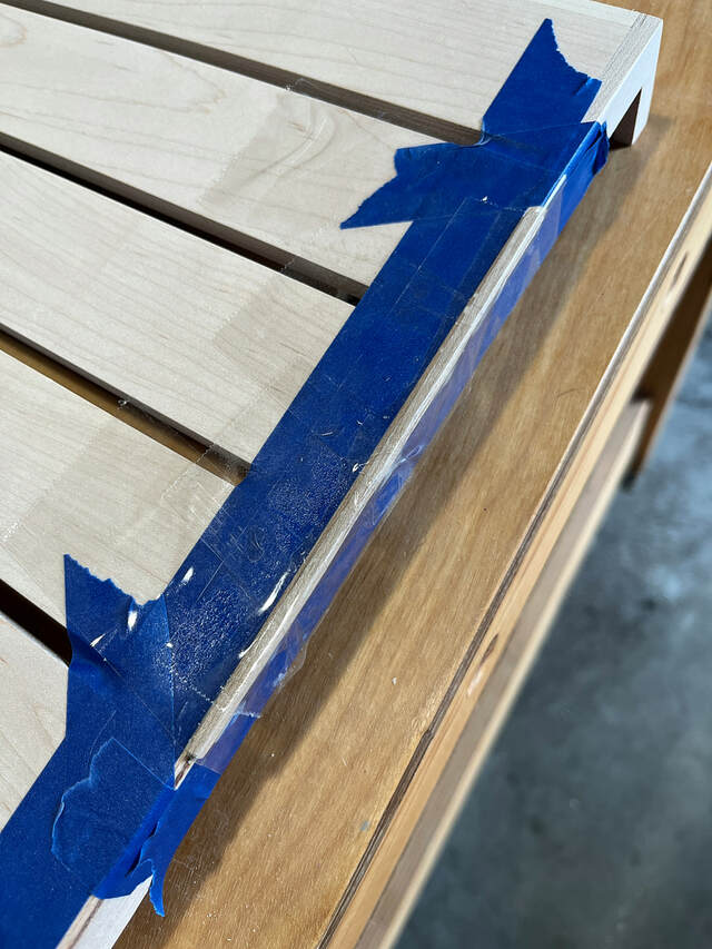
I spent half my workday in those blind alleys. Then I decided that I could use the handheld router without the edge guide and control the cut depth manually if I moved carefully. I would even attach my Jasper circle cutting jig to use as a big, wide router base to make sure the router didn’t tip. I put some painter’s tape over the slats so the base wouldn’t scratch anything.
That line of reasoning was a HUGE mistake. The big awkward router base made me think I couldn’t clamp on some sort of depth-limiting guide board on top of the panel. I didn’t think until later about clamping a sort of depth-limiting guide for the bit’s bearing underneath the panel. I just started the router and started cutting like a dumb fool.
It started out well enough. The bit was cutting easily, and I was controlling the depth. “This is going to work out okay,” I thought. As I moved the router to the right (over about 30”), I was unknowingly applying forward pressure and pushing the bit deeper into the side. When I finished the cut, but cut-off dropped away, and I thought I had done it.
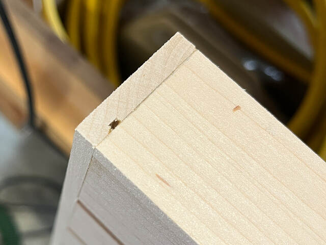
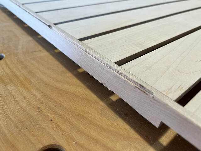
Then I looked at the frame’s top corner… It showed some burning (huh?) and at the far right, some burning and notching (WHAT?!!!). I knew I had messed up, but I didn’t know how.
What had happened is that the end of the collet nut contacted that corner of the frame side. On the left, it just grazed the corner and just burned it a bit. On the right, it went deeper and both burned and notched the corner. Here’s how it looked after I tried scraping and sanding away the burn marks.
I was able to clean up most of the damage by slightly rounding over the corner with sandpaper. The rounding was slightly more pronounced than the eased corners I had planned, but it wasn’t too bad. This edge is going to be about a quarter inch away from the corner between two walls, so it won’t be very visible. It didn’t have to be perfect—just good enough not to draw attention.
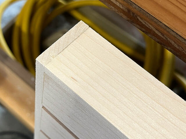
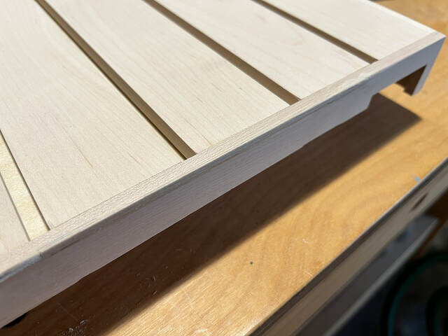
The notch on the right was too big to sand out. Luckily, I was able to salvage it by squaring it off and gluing in a filler strip.
After sanding the filler strip, the corner looked just good enough to keep me from trying more drastic solutions. At last, the panel was complete, and I was ready to start applying finish.
I used to work in commercial software development, and we worked closely with the customer support team. I remember talking to some of them after they had attended a training class on tactful, neutral communication. The instructor worked through sample statements and more tactful rewording. The one that stuck with me all these years was something like this:
Original statement: "Charlie is a real *ssh*le." Rewording: "Charlie is very detail oriented."
It is disheartening when you spend a lot of time working out the best approach and some detail bites you in the butt. You recovered nicely, though. Onward!
Are you trying to tell me something, LBD? Imagine how boring these build photos would be without all those blue pops of color from the painter’s tape. Gotta have something to draw the reader’s eye… The squeeze clamps and old yoga mat only go so far. 😀